


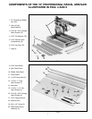

11
Fig. 15
Fig. 16
Fig. 17
Fig. 18
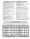
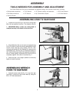
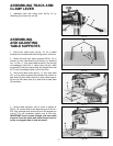
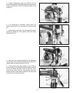
ASSEMBLING TRACK ARM
CLAMP LEVER
1. Assemble track arm clamp lever (A) Fig. 15, by
threading into clamp lock nut (B).
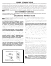
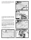
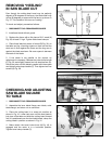
ASSEMBLING
AND ADJUSTING
TABLE SUPPORTS
1. Place front table board (A) Fig. 16, on a stable
surface with counterbored holes facing down, as shown.
2. Fasten left and right table supports (B) Fig. 16, to
bottom of front table board (A) as shown, by inserting
four 1/4-20 x 1″ long truss head screws (C) up through
counterbored holes (D) in table board (A) and table
supports (B). Secure in place using four flanged hex nuts
(E). Do not completely tighten nuts at this time.
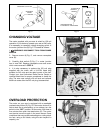
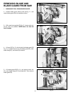
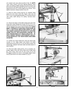
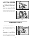
3. Place front table board (A) Fig. 17, onto saw base
(G), so that table supports (B) straddle the outside of
saw base (G) and three holes (H) in each table support
(B) line up with three slots (J) in each side of saw base
(G) as shown.
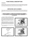
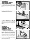
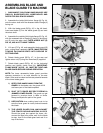
4. Secure table supports, one of which is shown at
(B) Fig. 18, to each side of saw base using six 5/16-18 x
5/8″ long carriage head screws (K) and six flanged hex
nuts (L). Do not completely tighten nuts at this time.
IMPORTANT: Insert screws through saw base table
supports from the inside and place flanged nuts on
screw on engaged side of base as shown.
B
A
B
A
C
E
D
D
G
J
B
H
A
B
L
K