


22
Fig. 67
Fig. 68
Fig. 69
Fig. 70
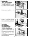
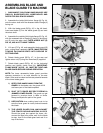
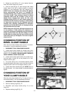
3. Rotate hex bolt (B) Fig. 67, in the desired direction
which the handle needs to be turned.
4. Push hex bolt (B) Fig. 67, back through hole. Make
certain head of hex bolt is seated properly in recessed
bushing (C), and reassemble track arm clamping lever.
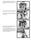
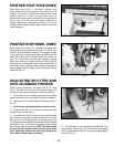
NOTE: If track arm clamping lever (A) Fig. 66, tightens
before approximately four turns, it is possible the
clamping bushings, one of which is shown at (C) Fig. 67,
may have rotated. These bushings should be seated
completely inside track (D) as shown. If they are not,
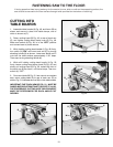
slightly loosen clamping lever (A) Fig. 66, and rotate
clamping bushing (C) Fig. 67, until it seats properly into
track (D) as shown. It may be necessary to rotate bushing
on clamp lever side also. Fig. 68, illustrates track arm
clamping lever assembly unassembled for illustration
purposes only. The flats (E) Fig. 68, on clamping bushings
(C) should face the front of saw.
NOTE: Clamp lever (A) Fig. 68, will begin to thread at one
of two positions. If after making the adjustment the
clamp lever (A) tightens 180 degrees from where desired,
slowly unscrew clamp lever (A) while holding in on hex
bolt (B). When the clamp lever (A) comes off hex bolt (B),
rotate clamp lever (A) 180 degrees. Then start to tighten
clamp lever (A).
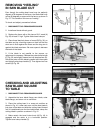
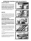
CHANGING POSITION OF
BEVEL CLAMP HANDLE
When the bevel clamp handle does not lock in a conven-
ient position, it can be repositioned as follows:
1. DISCONNECT TOOL FROM POWER SOURCE.
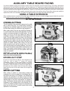
2. Loosen bevel clamp handle (A), release bevel index
release knob (B), and turn motor (C) to vertical position as
shown in Fig. 69. NOTE: IF BLADE GUARD CONTACTS
TABLE SURFACE, RAISE TRACK ARM.
3. Loosen bevel clamp handle (A) Fig. 69, several turns,
until hex head of screw (D) can be pushed out of hex-
shaped recess in yoke.
4. Turn screw (D) Fig. 69, in the desired direction which
the handle needs to be turned, one or two flats of the hex
head and push it back into hex-shaped recess in yoke.
5. Tighten bevel clamp handle (A) Fig. 69. NOTE: Screw is
left hand thread - turn clamp handle counterclockwise to
tighten.
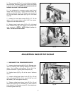
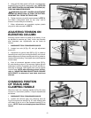
CHANGING POSITION OF
YOKE CLAMP HANDLE
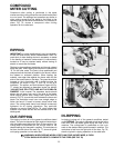
When the yoke clamp handle (A) Fig. 70, does not lock in a
convenient position, it can be repositioned as follows:
1. DISCONNECT TOOL FROM POWER SOURCE.
2 Remove retaining ring (B) Fig. 70.
3. Reposition yoke clamp handle (A) Fig. 70, on hex
clamp nut.
4. Replace retaining ring (B) Fig. 70.
B
D
C
A
C
E
B
B
A
C
D
A
B