


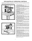

12
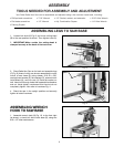
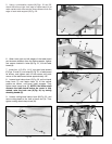
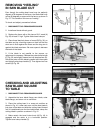
5. Using a combination square (M) Figs. 19 and 20,
check the left and right front edge of table board (A) to
make certain both sides are the same distance from the
edge of each table support (B) Fig. 20.
Fig. 19
Fig. 20
Fig. 21
Fig. 23Fig. 22
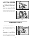
6. When both right and left edges of the table board
are the same distance from the table supports, tighten
four screws located in holes (N) Fig. 21, of front table
board (A).
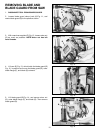
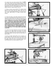
7. Insert four 1/4″-20 x 1-1/4″ long pan head screws
(P) Figs. 21 and 22, into holes (R) Fig. 21, of table board
as shown, and tighten each of the screws until each
corner of the table board raises approximately 1/8″.
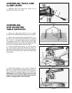
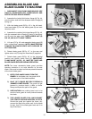
8. Loosen bevel clamp lever (S) Fig. 23, pull out bevel
index knob (T), and rotate motor (V) to the vertical
position as shown, until bevel index engages. Then
tighten bevel clamp lever (S). NOTE: If the motor shaft
contacts the table board before the motor is fully
rotated, raise the track arm (X) Fig. 24, by turning
elevating handle (C).
9. Loosen cutting-head clamp knob (W) Fig. 23, and
move cutting-head to the front of track arm (X). Then
tighten cutting-head clamp knob (W).
A
M
B
A
M
R
R
N
N
P
P
N
N
R
R
P
P
A
P
A
P
W
S
X
T
V