


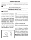

8
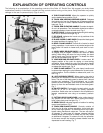
EXPLANATION OF OPERATING CONTROLS
The following is an explanation of the operating controls of the Delta 10" Radial Saw. We suggest you study these
explanations carefully to familiarize yourself with the controls before turning on the power. Doing otherwise may cause
damage to the saw or personal injury (Figs. 6 and 7).
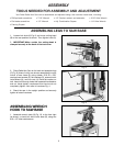
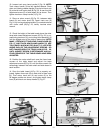
A. TABLE CLAMP KNOBS. Allows the operator to quickly
set the desired fence position. Fig. 6
B. TRACK ARM INDEXING RELEASE HANDLE. Releases
the indexing pin from the 0 degree and 45 degree positions
to allow the arm to rotate. Depress handle to release the
index pin. Fig. 6
C. TRACK ARM ELEVATING HANDLE. Controls the depth-
of-cut in all operations. Turn the handle clockwise to raise or
counterclockwise to lower the track arm. Fig. 6
D. MITER SCALE. Indicates degrees left and right for setting
track arm to desired miter angle. Fig. 6
F. RIP SCALE. Indicates the in and out rip positions of the
cutter-head. Fig. 6
G. BLADE GUARD CLAMP KNOB. Clamps the blade guard
at rotated positions for ripping. Fig. 6
H. BEVEL CLAMP HANDLE. Controls tilt of motor for bevel
cutting operations. Locks motor at any desired angle on the
bevel scale. Lift handle to loosen and push down to lock.
Fig. 6
J. BEVEL INDEX RELEASE KNOB. Locates 0 degree,
45 degree, and 90 degree. Positions the motor for bevel
setting. When tilting the motor for bevel cutting, the bevel
clamp handle must first be loosened. To release the index
pull out on the release knob. Fig. 6
K. YOKE INDEXING RELEASE LEVER. Locates each 90
degree position of the yoke for ripping or cross-cutting
operations. When rotating the yoke, the yoke clamp handle
must first be loose. Push the release lever either up or down
to release the indexing pin. Fig. 6
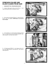
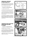
L. YOKE CLAMP HANDLE. The yoke clamp handle must
be loose when rotating the yoke between the rip and cross-
cutting position. Pull the handle to release and push it to
lock. Fig. 7
M. ANTI-KICKBACK DEVICE. When ripping, the yoke is
positioned and clamped so that the blade is parallel to the
fence. The rear of the blade guard is rotated until it almost
touches the workpiece. The anti-kickback rod is then
lowered so that the fingers catch and hold the workpiece.
Never rip from the anti-kickback end of the blade guard.
Fig. 7
N. ON-OFF SWITCH. Conveniently located switch can be
turned on or off in an instant for added operation
protection. Switch also can be locked in the off position to
prevent unauthorized use using an accessory padlock.
Fig. 7
P. CUTTING-HEAD CLAMP KNOB. Locks cutting-head at
any position on the track arm. When ripping the cutting-
head, clamp knob must be tight. Fig. 7
R. BEVEL SCALE. Indicates degrees of rotation for setting
motor bevel positions. Fig. 7
S. TRACK ARM CLAMP HANDLE. Controls rotation of
track arm for all miter cutting operations. Locks track arm
at any miter angle position. To rotate track arm to the right,
loosen clamp handle and rotate arm. The arm will stop at
45 degrees. To rotate past 45 degrees, depress indexing
release handle and continue to rotate; arm will only rotate
an additional 5 degrees. To rotate to the left, the operation
is the same except the indexing release handle must be
depressed to start rotating. Fig. 7
Fig. 6
A
J
D
K
G
F
H
C
B
Fig. 7
S
L
N
M
R
P