


10
Fig. 43
Fig. 44
F
G
H
F
G
Fig. 39
Fig. 40
Fig. 41
Fig. 42
N
P
R
V
S
N
P
R
X
Y
W
C
D
E
C
E
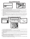
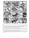
NOTE: Never operate the sliding table with the table lock/stop bracket removed.
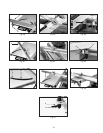
15. Place the special threaded bolt (N) Fig. 39 through the hole in the slide bracket (P) and the spacer and flat washer (R),
then through the bushing (S) in the table and frame. Fasten in place with a flat washer and knob (V) from underneath the
table. Make sure that the hex head on the bolt seats in the hex on the slide bracket.
16. Place the special threaded bolt (N) Fig. 40 through the hole in the remaining slide bracket (P) and the spacer (R) then
down through the hole in the sliding bracket (W). Fasten in place with a flat washer (X) and locking lever (Y).
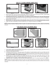
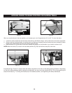
17. Insert the rear fence cam (C) Fig. 41 into hole (D) in the bracket. Tighten the set screw (E) Fig. 41 and Fig. 42 to hold the
cam (C) in place. Adjustment to the cam (C) will be made later.
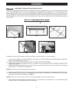
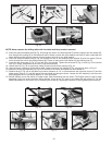
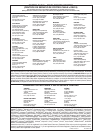
18. Attach fence (F) Fig. 43 to right fence clamp (G) and into left fence clamp (H) Fig. 44.
19. After the fence is attached to the sliding table, tighten the fence lock handle (G) Fig. 44 and lock knob (J) Fig 47.
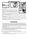
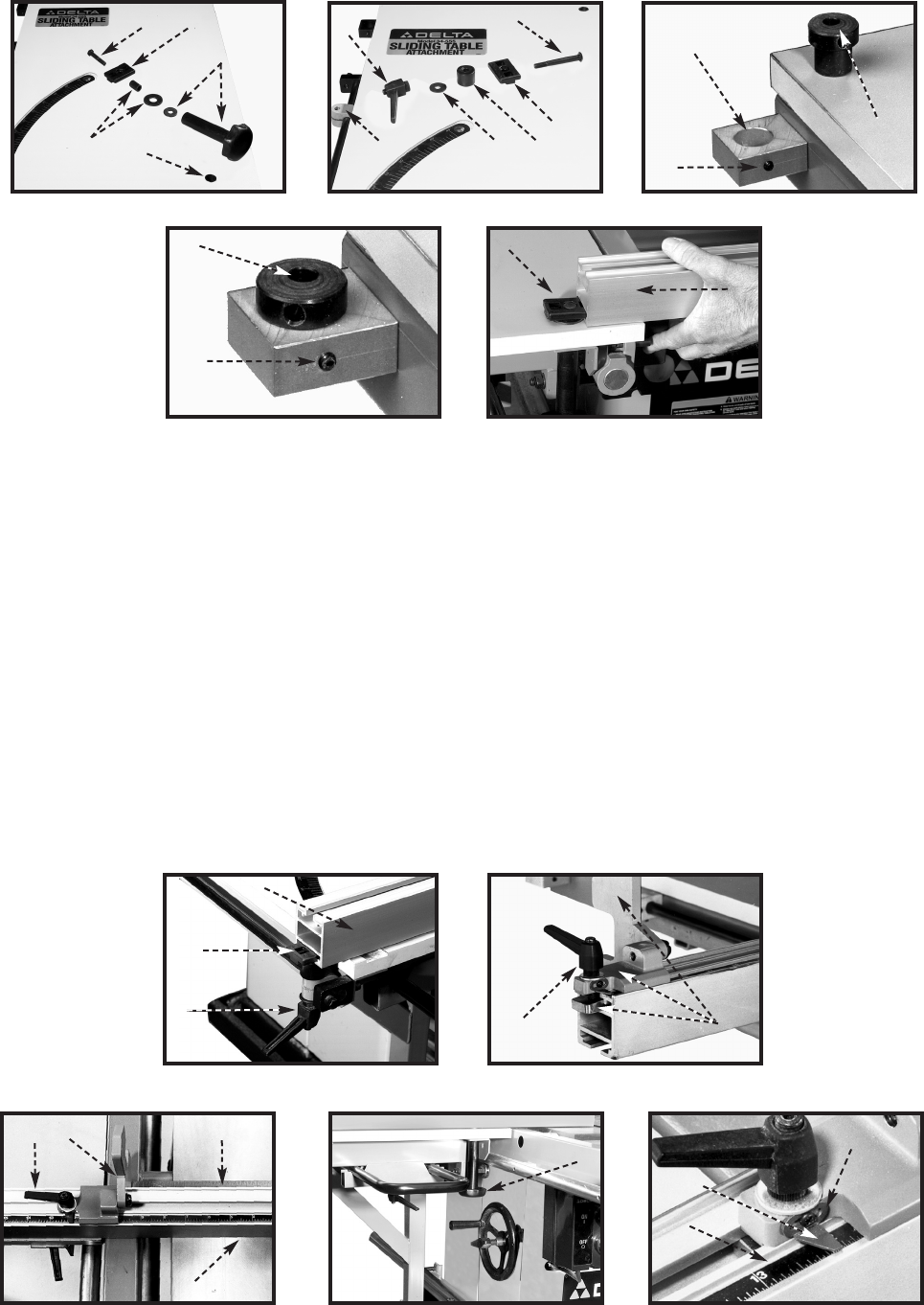
20. Attach the fence stop assembly (K) Fig. 45 to the top of the fence and tighten the lock handle (L).
21. Position fence (F) Fig. 46 on the table to provide a clearance of 1/4" or more between the right end of fence (F) and the
blade guard. Place a 12" rule (M) against the saw blade and along the fence. Loosen the lock handle (L) and move the
stop (N) against end of rule (M) to place it 12" from the blade.
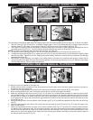
22. Decide whether to use the metric or English scale. Peel the backing from the scale. (The English scale is used in these
examples.) Apply the scale inside the fence channel, lining up the 12" mark on the scale with the pointer (O) Fig. 48.
Make adjustments to the pointer (O) by loosening the screw (R), adjusting the pointer (O) and tightening the screw (R).
Fig. 45
Fig. 46
L
K
L
N
M
Fig. 48
P
O
R
F
SCALE
J
Fig. 47