


6
FOR 10" CONTRACTOR’S SAWS
(CURRENT STYLE)
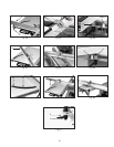
Fig. 9
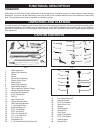
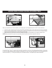
Fig. 10
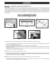
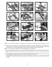
1. If your switch is attached to the left extension wing, remove it. (After installation of the sliding table, re-attach
the switch to the location shown in Fig. 9.)
2. Remove the left-hand table extension. (It will not be used with the Sliding Table.)
3. Confirm that the rail/bracket has been assembled as shown in Fig. 9, and that the short end of the rail (stud
closest to the end) is on the right. (If the rail has been previously attached with the long end of the rail to the
right, remove the bracket, turn the rail 180 degrees, and re-attch the bracket.
4. Locate the lower rail assembly (Fig. 9), two 1" hex head screws, two flat washers, two special washers, and
two hex nuts.
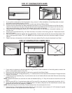
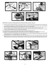
5. Attach the rail as assembled (Fig. 10). Place the studs in the holes on the lower guide rail. These studs should
be 21-3/4" apart.
6. Hold the lower rail assembly against the saw cabinet (Fig. 10) and mark and drill the two mounting holes in the
side of the leg panels using a 7/16" drill. NOTE: Hold the rail assembly level with the bottom edge of the saw
cabinet.
7. Fasten the lower rail assembly to the left side of the saw cabinet (Fig.10), using the hardware from Step 1.
Fig. 11
A
Fig. 14
F
G
E
FOR 10" CONTRACTOR II SAWS ONLY
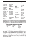
Fig. 12
Fig. 13
F
D
E
B
B
C
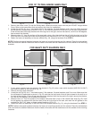
1. If your switch is attached to the left extension wing, remove it. (After installation of the sliding table, re-attach the
switch to the location shown in Fig. 6C.)
2. Remove the left-hand table extension. (It will not be used with the Sliding Table.)
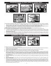
3. Remove the two top left carriage bolts (A) Fig. 11, washers and nuts from saw stand and discard. Enlarge the holes
using a 7/16" drill bit.
4. Locate the lower rail assembly (Fig. 12), and remove one nut and washer (B) from each side. Remove the mounting
bracket (C) Fig. 12.
NOTE: Discard the bracket, but save the two nuts and washers (B) Fig. 12. They will be used to mount the rail to the
stand.
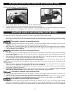
5. Move the stud (E) Fig. 13 on the lower guide rail (F) to hole (D) in the guide rail. Hole spacing should be 18-1/4".
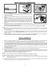
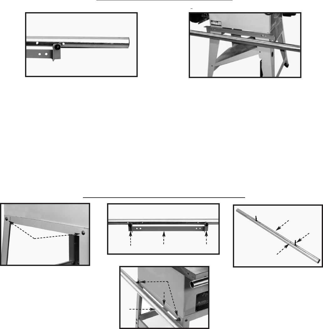
6. Attach the lower guide rail (E) Fig. 19 to the two holes in the stand, using the two flat washers and nuts that were
removed from the lower rail assembly in STEP 2.
NOTE: Place the long end of rail (E) Fig. 19 (stud farthest from the end) toward the front.
7. Tighten the four nuts that attach the guide rail (F) Fig. 19 to the stand. Leave a space of 2-1/8" between the guide
rail and the stand. Final adjustments will be made later.