


99
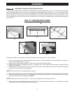
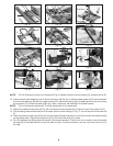
Fig. 27
Fig. 28
Fig. 29
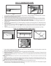
Fig. 30
Fig. 31
L
M N
C
E
B
D
A
R
Q
Q
P
S
P
W
U
T
S
V
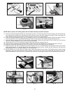
Fig. 32
Fig. 33
Fig. 34
P
S
X
S
E
Z
A
Y
F
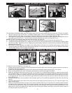
Fig. 35
Fig. 36
E
F
B
D
C
C
H
G
Fig. 37
F
Y
J
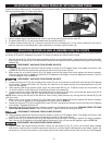
Fig. 38
K
M
L
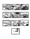
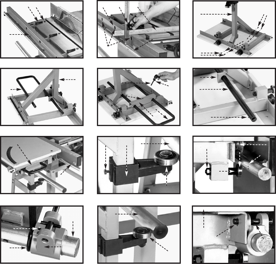
For Old Contractor’s Saws, turn bracket (A) Fig. 34 upside down so that the bearing (Y) contacts the rail (F).
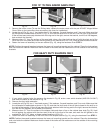
10. Adjust the two lower bearings, one of which is shown at (B) Fig. 35, so that the upper guide rail (C) will be between
the two lower bearings (B) and two upper bearings (D). Adjust the bearing (B) by loosening the nut (E) and turning
the eccentric (F) to move the bearing (B) up or down. Adjust the rear bearing in the same manner.
This is a temporary adjustment. The final adjustment will be made later.
11. Attach the rubber bumper stop (G) Fig. 36, and table lock/stop bracket (H) to the front end of the upper rail (C).
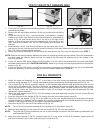
12. Pull the sliding table toward the front of the saw until the lower bearing (Y) Fig. 37 is near the end of the lower rail
(F).
13. Push the rubber bumper stop (G) Fig. 36 and the table lock/stop bracket (H) in until they contact the upper bearing
on the sliding table. Tighten the set screw (J) Fig. 36 to hold the stop (H) in place.
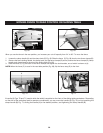
14. Fig. 38 illustrates the sliding table (K) locked in the forward position. The lock pin (L) is moved to the left through
the hole (M) in the table bracket to lock the table in place. To slide the table on the rail, move the lock pin (L) to
the right.
NOTE:
NOTE: