


7
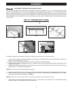
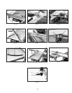
Fig. 15
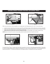
Fig. 16
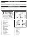
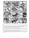
FOR 10" TILTING ARBOR SAWS ONLY
1. Remove the motor cover. (To use the Sliding table, replace the motor cover with the part #734557 Hinged Motor
Cover. Refer to the instructions that accompany the cover for installation.)
2. Locate the rail (Fig.15), two 1" hex head screws, 2 flat washers, 2 special washers, and 2 hex nuts. Make sure that
the rail/bracket is assembled as shown in Fig. 15, and that the short end of the rail is on the right of the bracket.
(If the rail has been previously attached with the long end to the right, remove the bracket, turn the rail 180 degrees,
and re-attach the bracket.)
3. Measure down 21" from the surface of the saw table, draw a line, then hold up the rail (with the short end of the
rail to the front of the saw) and mark the drill guides on the marked line. Drill 7/16" holes at these marked locations.
4. Fasten the lower rail assembly to the saw cabinet (Fig. 16), using the hardware From STEP 1.
NOTE: Position the special washers between the lower rail mounting bracket and the cabinet. Place the lockwashers
and nuts inside the cabinet. Make sure that the head of the bolts and flat washers are on the outside of the mounting
brackets.
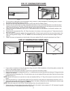
Fig. 17
J
J
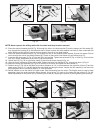
FOR HEAVY DUTY SHAPERS ONLY
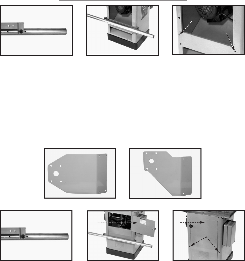
Fig. 20
Fig. 21
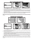
K
Fig. 22
K
J
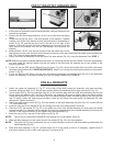
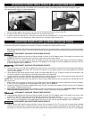
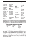
1. If your switch bracket looks the same as the bracket in Fig 18, order a new switch bracket (#432-02-014-0017)
that looks the same as the bracket in Fig. 19 .
2. Remove the front table extension.
3. Locate the rail (Fig.20), two 1" hex head screws, 2 flat washers, 2 special washers, and 2 hex nuts. Make sure that
the rail/bracket is assembled as shown in Fig. 20, and that the short end of the rail (stud closest to the end) is on
the right of the bracket. (If the rail has been previously attached with the long end to the right, remove the bracket,
turn the rail 180 degrees, and re-attach the bracket.)
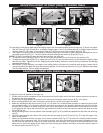
4. Measure down 21" from the surface of the shaper table and draw a line on the cabinet door side (Fig. 22). Hold
the rail against the cabinet with the short end of the rail to the front of the saw, and mark the drill guides on the
marked line. Drill 7/16" holes at these marked locations (J) Fig. 22.
5. Fasten the lower rail assembly to the front side of the shaper cabinet (Fig. 21), using the hardware From STEP 1.
NOTE: Position the special washers between the lower rail mounting bracket and the cabinet. Place the lockwashers
and nuts inside the cabinet. Make sure that the head of the bolts and flat washers are on the outside of the mounting
brackets.
Fig. 18
Fig. 19