


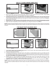
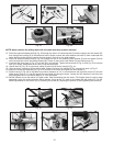
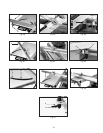
1. Attach the upper rail assembly (L) Fig. 27 to the side of the table where the extension wing was previously
mounted, using the three 2-1/2" socket head screws (M) and lockwashers (N) through the holes (C) Fig. 28.
2. Use a square (D) Fig. 28 with a straight edge (A) on the machine table with the other end extending over the top
of the upper rail assembly (B). The top of the upper rail assembly (B) must be slightly below the table surface.
Check the square (A) to confirm that the rail (E) is the same distance below the table surface at the front and the
rear. To adjust, loosen the three screws located in holes (C) and adjust the upper guide rail assembly (B). After
adjustment, tighten screws (C).
4. Attach the table support frame (P) Fig. 29 to the bottom of the table assembly using the four 3/4" screws (Q) and
1/4" lockwashers (R).
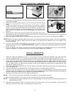
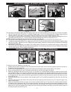
5. Insert the long end of the handle (S) Fig. 30 through the hole in the table support frame (P).
6. Place the 5/16" flat washer (T) Fig. 31 on the shaft end of the lock handle assembly (U) and place the handle
support bracket (V) in position over the handle (S). Insert the threaded end of the handle assembly (U) through the
hole (W) in the support bracket (V) and tighten the handle assembly (U).
7. Insert the roll pin (X) in the end of the handle rod (S) Fig. 32.
The roll pin (X) prevents the handle (S) from pulling out of the support frame (P).
8. Slide the table assembly on the upper rail with the handle (S) Fig. 33 in the front position.
The guide rail (C) must be between the two V roller bearings and the two flat roller bearings underneath the
table assembly (Fig 35).
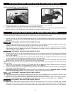
9. Make sure lower bearing (Y) Fig. 34, contacts lower rail (F) in the center of the rail. If necessary, loosen screw (Z)
and move bracket (A) up or down until bearing (Y) contacts rail (F).
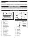
FOR ALL PRODUCTS
NOTE:
NOTE:
8
Fig. 25
J
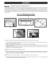
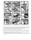
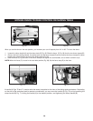
FOR 10" RIGHT-TILT UNISAWS ONLY
Fig. 23
Fig. 24
1. If the switch is mounted to the left table extension, remove the switch and
discard the hardware.
2. Remove the left-hand table extension. (It will not be used with the sliding
table.)
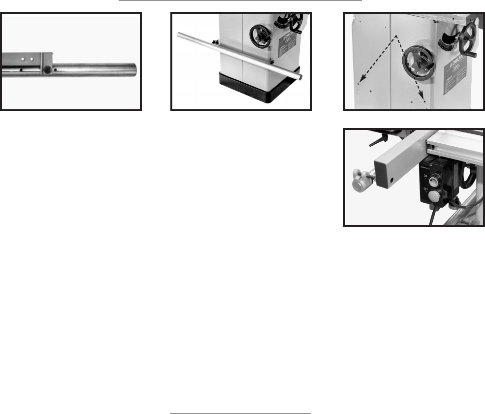
3. Locate the rail (Fig.23), two 1" hex head screws, 2 flat washers, 2 special
washers, and 2 hex nuts. Make sure that the rail/bracket is assembled as
shown in Fig. 20, and that the short end of the rail is on the right of the
bracket. (If the rail has been previously attached with the long end to the
right, remove the bracket, turn the rail 180 degrees, and re-attach the
bracket.)
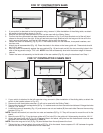
4. Measure down 19-3/4" from the top surface of the saw table, draw a line,
then hold up the rail (with the short end of the rail to the front of the saw). Mark the drill guides on the marked line.
Drill 7/16" holes at these marked locations.
5. Fasten the lower rail assembly to the left side of the saw cabinet (Fig. 24), using the hardware From STEP 1.
NOTE: Position the special washers between the lower rail mounting bracket and the cabinet. Place the lockwashers
and nuts inside the cabinet. Make sure that the head of the bolts and flat washers are on the outside of the
mounting brackets.
6. If your unit has the GPE switch (different from the one in Fig. 26), remove the bracket from the switch and attach
the sheet metal bracket (#9 in CARTON CONTENTS). Attach it by moving from the original position to the position
shown in Fig. 26.
7. If your unit has the LVC switch, use the front rail mounting hardware and secure it with the nut on the backside.
Attach this assembly in the same location and with the same hardware as in STEP 6.
Fig. 26