


10
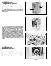
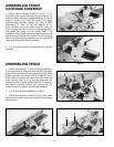
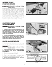
ASSEMBLING FENCE
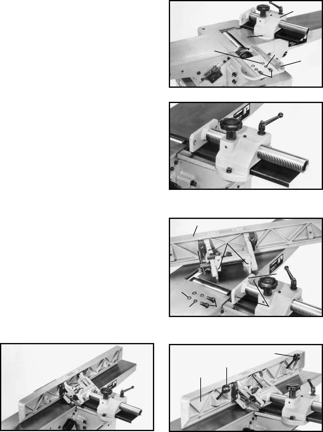
CARRIAGE ASSEMBLY
1. Fasten fence carriage assembly (A) Fig. 15, to
cutterhead pulley guard/carriage mounting bracket (C).
Align the holes in the fence carriage assembly (A) one of
which is shown at (D), with the holes in the pulley
guard/carriage mounting bracket (C). Place a M8.1
lockwasher (E), then an M8 flat washer on an
M8x1.25x20mm hex socket head screw (B). Insert the
screw through the hole in the fence carriage assembly,
and thread the screw into the tapped hole in the
cutterhead pulley guard/carriage mounting bracket and
tighten securely. Repeat this process for the remaining
hole in the fence carriage assembly and the cutterhead
pulley guard/carriage mounting bracket.
2. Fig. 16, illustrates fence carriage assembly properly
mounted.
Fig. 15
D
A
C
B
Fig. 16
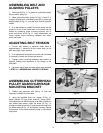
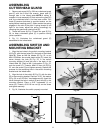
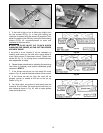
ASSEMBLING FENCE
1. Fasten fence (A) Fig. 17, to fence carriage assembly
(C) through holes (D). Align the two holes (G) in the fence
with the two holes (D) in the carriage assembly (C). Place
a M8.1 lockwasher (E), then an M8 flat washer (F), on an
M8x1.25x25mm hex socket head screw (B). Insert the
screw through hole (D) in the carriage assembly and
thread the screw into the tapped hole (G) in the fence,
and tighten securely. Repeat this process for the
remaining hole in the fence and carriage assembly.
2. Fig. 18 illustrates fence properly mounted.
3. Thread shorter fence handle (E ) Fig.19, into infeed
end of fence (A) and longer fence handle (G) into outfeed
end as shown.
Fig. 17
A
B
C
D
Fig. 18
Fig. 19
A
E
G
E
F
E
F
G