13
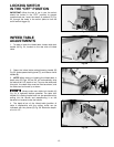
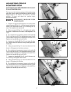
LOCKING SWITCH
IN THE “OFF” POSITION
IMPORTANT: When the tool is not in use, the switch
should be locked in the “OFF” position to prevent
unauthorized use. Insert the shank of padlock (C) Fig.
33, through the holes in the switch plate to lock the
on/off switch trigger (A).
Fig. 33
C
A
INFEED TABLE
ADJUSTMENTS
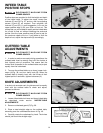
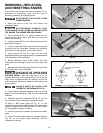
1. To raise or lower the infeed table, loosen table lock
handle (A) Fig. 34, located on the rear side of infeed
table.
Fig. 34
A
Fig. 35
B
C
D
Fig. 36
E
D
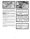
2. Grasp the infeed table raising/lowering handle (B)
Fig. 35, and squeeze locking lever (C), and raise or lower
handle (B).
3. NOTE: When raising or lowering the infeed table, a
depth stop (D) Figs. 35 and 36, will automatically stop
the table at an 1/8" depth-of-cut. To move the table past
this point, the depth stop must be lifted as shown, and
the table can be moved up or down.
Always make sure table lock handle (A)
Fig. 34, is tightened before operation. The table lock
handle (A) is spring-loaded and can be repositioned by
pulling out the handle and repositioning it on the
serrated nut located under the handle.
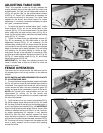
4. The depth-of-cut of the infeed table (position of
table in relationship with the cutting circle) can be
indicated with the pointer (E) Fig. 36. Maximum depth-
of-cut is 1/2".


