


16
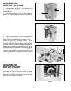
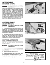
ADJUSTING TABLE GIBS
“Gibs”’ are provided to take up all play between the
mating dovetail ways of the base and the infeed and
outfeed tables. The ”gib” for the infeed table is shown at
(A) Fig. 46, and the “gib” for the outfeed table is shown
at (B) Fig. 47. Proper “gib” adjustment is necessary for
the correct functioning of the jointer. The “gibs” were
adjusted at the factory and should require no further
adjustment. If, however, it becomes necessary to adjust
the “gibs”, proceed as follows:
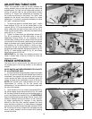
1. To adjust the infeed or outfeed table “gibs”, loosen
three locknuts (F) Fig. 46, for the infeed table or two
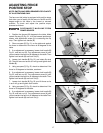
locknuts (G) Fig. 47, for the outfeed table. For the infeed
table, make sure the table locking lever (H) Fig. 46, is
loose. For the outfeed table, make sure the table locking
screw (E) Fig. 47, is loose.
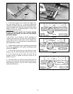
2. Tighten or loosen three gib adjustment screws (C)
Fig. 46, as necessary for the infeed table or two gib
adjustment screws (D) Fig. 47, as necessary for the
outfeed table; starting with the lower screw first and as
you proceed to the top screw, gently raise the outboard
edge of the table that is being adjusted. This will offset
any tendency for the table casting to “droop or sag”’
and permit the gib to be adjusted to a secure fit. After
the gibs have been adjusted, tighten locknuts (F) Fig. 46,
(G) Fig. 47, table locking screw (E) Fig. 47, and infeed
table locking lever (H) Fig. 46.
IMPORTANT: Do not leave the adjusting screws too
loose. It should take a little bit of effort to move the
tables up or down.
Fig. 46
F
C
F
C
A
Fig. 47
D
G
E
D
G
B
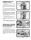
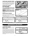
FENCE OPERATION
The fence can be moved across the table and can tilt
45 degrees right or left at any position on the table as
follows:
NOTE: SWITCH HAS BEEN REMOVED FOR CLARITY
OF ILLUSTRATIONS ONLY.
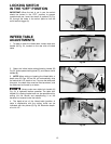
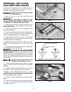
1. To move the fence across the table, loosen lock handle
(A) Fig. 48, and turn knob (B) until desired fence location
is reached. Then tighten lock handle (A). As the fence is
moved across the table, the rear cutterhead guard (C)
covers and guards the cutterhead in back of the fence.
NOTE: Lock handle (A) is spring-loaded and can be
repositioned by pulling up on the handle and
repositioning it on the serrated nut located underneath
the hub of the handle.
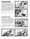
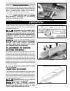
2. To tilt the fence in or out, loosen lock handle (D) Fig.
48. While holding fence tilting handle (E) Fig. 49, rotate
90° flip stop (G) and tilt the fence to the desired angle, in
or out, and tighten lock handle (D) Fig. 48. IMPORTANT:
When cutting bevels and the angle is small, there is little
difference whether the fence is tilted in or out; however,
at angles approaching 45 degrees it may become
difficult to hold the work securely against the fence
when the fence is tilted out. In these cases we suggest
that the fence be tilted toward the table, as shown in Fig.
50. The fence will form a V-shape with the tables and the
work is easily pressed into the pocket while passing
across the knives.
D
C
B
A
Fig. 48
Fig. 49
G
E
H