


18
REMOVING, REPLACING,
AND RESETTING KNIVES
If the knives are removed from the cutterhead for re-
placement or sharpening, care must be used in
removing, replacing, and resetting them.
DISCONNECT MACHINE FROM
POWER SOURCE.
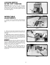
1. Move the fence to the rear and remove the
cutterhead guard.
BE EXTREMELY CAREFUL THAT
YOUR HANDS DO NOT COME IN CONTACT WITH
THE KNIVES. THE KNIVES ARE VERY SHARP.
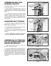
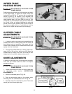
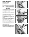
2. Using wrench (A) Fig. 54, slightly loosen the four
locking screws (B) in each knife slot by turning the
screws (B) clockwise.
3. Loosen screws (B) Fig. 54, further and remove knife
and knife locking bar.
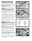
4. Fig. 55, shows the knife (C) and knife locking bar (D)
removed from the cutterhead. Remove the remaining
two knives and locking bars, in the same manner.
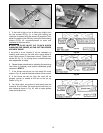
5. Using wrench (E) Fig. 55, lower the two knife
adjustment blocks by turning screws (F) counterclockwise
in all three slots of the cutterhead.
6. Before replacing knives make certain the knife
locking bars are thoroughly clean and free of gum and
pitch.
7. Replace the knife locking bars (D) Fig. 55, and knives
(C) into each slot in the cutterhead.
CARE MUST BE TAKEN WHEN
INSERTING THE KNIVES AS THE CUTTING EDGES
ARE VERY SHARP. Push the knife down as far as
possible and snug up the screws (B) Fig. 54, by turning
each screw counterclockwise just enough to hold the
knife in position. Replace the remaining two knifes in the
same manner.
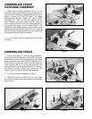
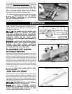
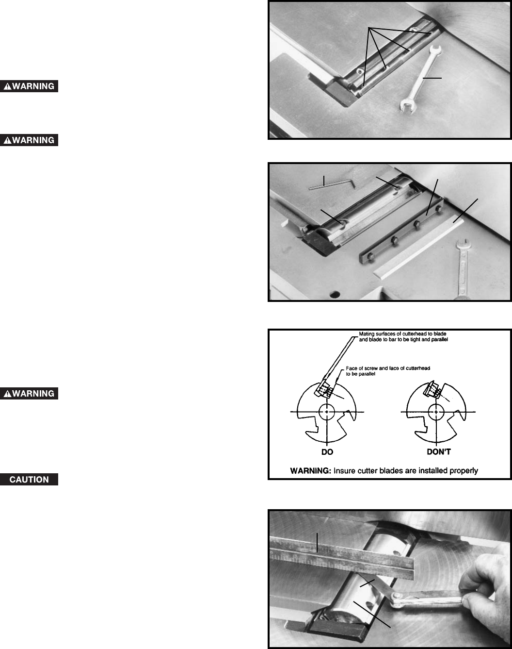
KNIVES MUST BE INSTALLED
CORRECTLY AS SHOWN IN FIG. 56.
8. The knives are adjusted correctly when the cutting
edge of the knife extends out .060” from the cutterhead
diameter.
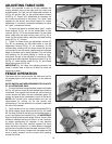
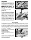
9. Carefully rotate the cutterhead (G) Fig. 57, until the
round portion of the cutterhead is on top as shown.
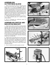
10. Place a .060” feeler gage (H) Fig. 57, on the
cutterhead and using a straight edge (J) on the rear table
adjust the height of the rear table until it is .060” above
the cuttinghead diameter, as shown.
11. Lock the rear table in position and remove the feeler
gage.
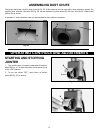
12. Lower the infeed table and place a straight edge (J)
Fig. 58, on the outfeed table extending over the
cutterhead as shown.
B
A
Fig. 54
Fig. 55
E
Fig. 56
Fig. 57
J
H
G
C
D
F
F