


17
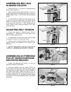
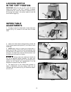
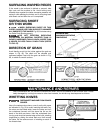
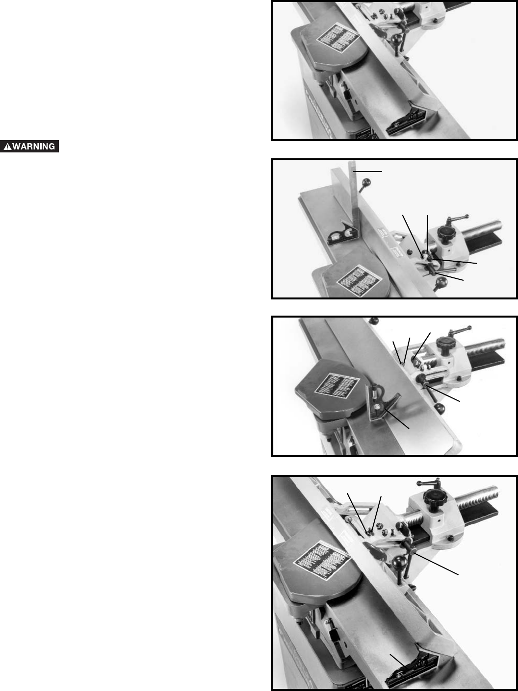
ADJUSTING FENCE
POSITIVE STOP
NOTE: SWITCH HAS BEEN REMOVED FOR CLARITY
OF ILLUSTRATIONS ONLY.
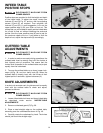
The fence on this jointer is equipped with positive stops
that allow you to rapidly tilt the fence to the 90 and 45
degree angle to the table in the inward or outward
position. To check and adjust the positive stops,
proceed as follows:
DISCONNECT MACHINE FROM
POWER SOURCE.
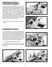
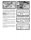
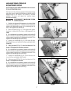
1. Position the fence at 90 degrees to the table. Make
certain flip stop (G) Fig. 51, is in the lowered position as
shown, and adjustment screw (A) is contacting the flip
stop. Then tighten lock handle (B).
2. Place a square (C) Fig. 51, on the table and against
the fence to determine if the fence is 90 degrees to the
table.
3. If an adjustment is necessary, loosen lock handle (B)
Fig. 51, and lock nut (D). Turn adjustment screw (A) until
you are certain the fence is 90 degrees to the table. Then
tighten lock handle (B) and lock nut (D).
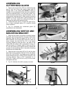
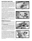
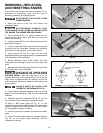
4. Loosen lock handle (B) Fig. 52, and rotate flip stop
(G). Then tilt fence out as far as it will go and tighten lock
handle (B).
5. Using a square (C) Fig. 52, check to determine if the
fence is 45 degrees to the table, as shown.
6. If an adjustment is necessary, loosen lock handle (B)
Fig. 52, and lock nut (E). Turn adjustment screw (H) until
you are certain the fence is 45 degrees to the table. Then
tighten lock handle (B) and lock nut (E).
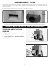
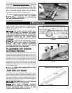
7. Loosen lock handle (B) Fig. 53, and tilt fence as far
in as it will go and tighten lock handle.
8. Using a square (C) Fig. 53, check to determine if the
fence is 45 degrees to the table.
9. If an adjustment is necessary, loosen lock handle (B)
Fig. 53, and lock nut (J). Turn adjustment screw (K) until
you are certain the fence is 45 degrees to the table.Then
tighten lock handle (B) and lock nut (J).
Fig. 50
Fig. 51
B
G
AD
C
Fig. 52
C
B
H
E
G
Fig. 53
B
C
K
J