


10
Fig. 15
Fig. 16
Fig. 14
Fig. 13
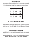
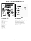
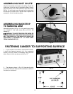
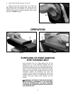
ASSEMBLING DUST CHUTE
Align the three holes in the dust chute (A) Fig. 13 with the
three holes in the left side of the sanding base. Place a
M5.3 flat washer onto a M5x.08x10mm pan head screw
(B) Fig. 13, and insert screw through hole in dust spout
and thread into taped hole in sander base. Repeat this
process for the two remaining holes.
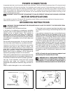
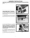
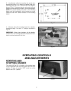
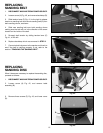
ASSEMBLING BACKSTOP
TO SANDING ARM
Assemble backstop (A) Fig. 14, to the sanding arm using
the 1/4-20x1/2" hex head screw (B) and 5/16" flat
washer (C).
WARNING: TO AVOID TRAPPING THE WORK OR
FINGERS BETWEEN THE BACKSTOP AND SANDING
BELT, THE EDGE (D) OF THE BACKSTOP SHOULD BE
POSITIONED A MAXIMUM OF 1/16 INCH AWAY
FROM SANDING BELT (E).
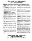
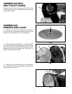
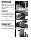
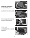
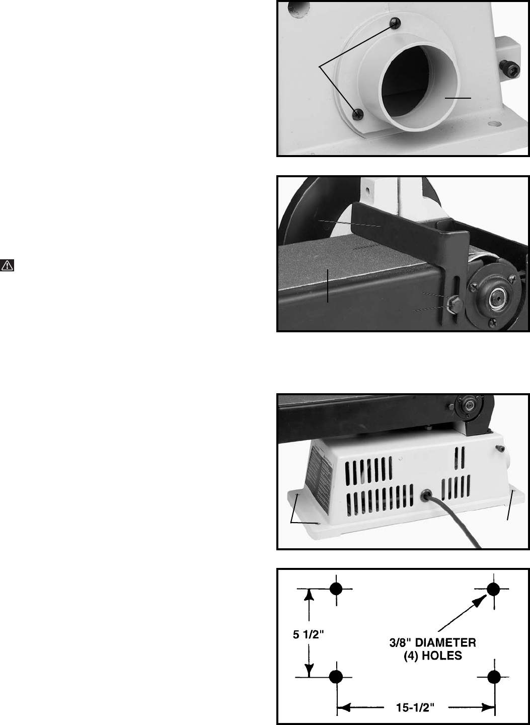
FASTENING SANDER TO SUPPORTING SURFACE
1. If your sander is to be used in a permanent location,
it should be fastened securely to a firm supporting
surface, such as a stand or workbench using the four
holes, three of which are shown at (A) Fig. 15.
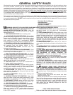
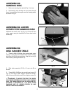
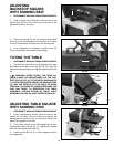
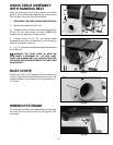
2. The diagram, shown in Fig. 16, illustrates the size
and center to center distance of the holes to be drilled in
the stand or workbench.
A
B
B
C
E
D
A
A
A