


15
Fig. 39
Fig. 38
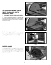
Fig. 37
Fig. 36
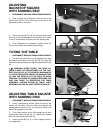
USING TABLE ASSEMBLY
WITH SANDING BELT
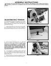
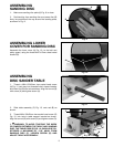
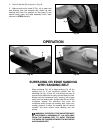
When the sanding arm (A) Fig. 36, is used in the vertical
position, the complete table assembly (B) can be moved
from the disc unit to the belt unit as follows:
1. DISCONNECT MACHINE FROM POWER SOURCE.
2. Remove the backstop (C) Fig. 36.
3. Thread the M8x1.25x20mm hex socket head screw
(D) Fig. 36, into base casting as shown. NOTE: Only
thread screw (D) partway into base casting.
4. Loosen screw (E) Fig. 36, and remove table
assembly (B) from disc unit. Insert bar (F) into hole (G) on
belt unit and tighten screw (D).
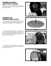
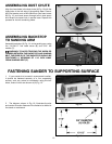
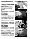
5. Fig. 37, illustrates the table assembly (B) assembled
to the belt unit.
WARNING: THE TABLE EDGE (G) MUST BE
POSITIONED A MAXIMUM OF 1/16 INCH AWAY
FROM THE SANDING BELT (H) TO AVOID TRAPPING
THE WORK OR FINGERS BETWEEN THE TABLE AND
SANDING BELT.
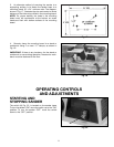
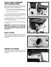
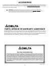
DUST CHUTE
A dust chute (A) Fig. 38, is supplied with your sander and
can be connected to a standard shop vacuum hose. The
outside diameter of the opening of the dust spout is 2-
1/2 inches.
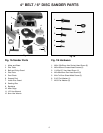
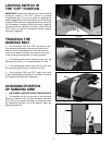
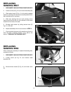
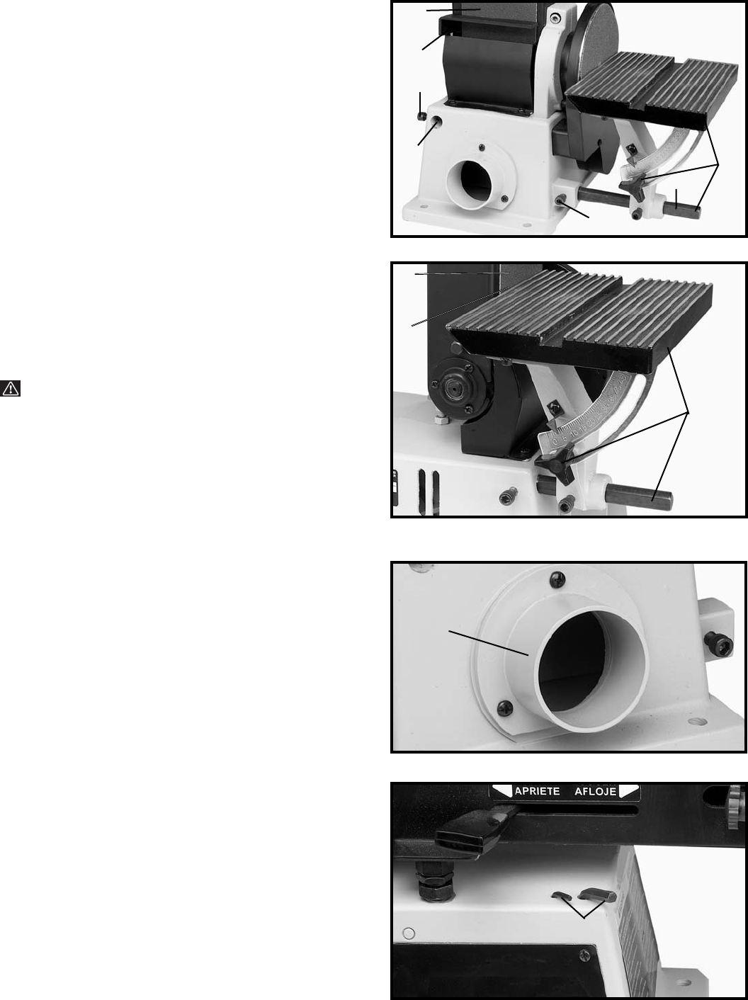
WRENCH STORAGE
Two holes are provided in the base casting and are used
for storing the two wrenches (A) Fig. 39, supplied with
the sander.
A
C
D
G
E
F
B
H
G
B
A
A