


14
Fig. 32
Fig. 33
Fig. 34
Fig. 35
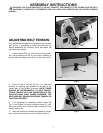
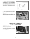
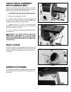
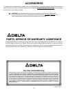
3. If an adjustment to the table is necessary, loosen
the three screws (B) Fig. 34, that fasten the table to the
table mounting bracket and trunnion and adjust the table
accordingly - then tighten the three screws (B).
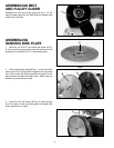
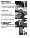
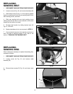
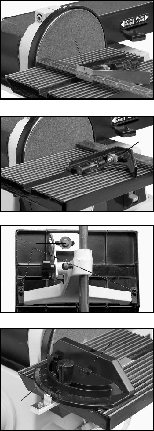
MITER GAGE
A miter gage (A) Fig. 35, is supplied with your machine
and is used with the disc table. The miter gage body (A)
can be rotated right or left for angle or miter sanding by
loosening lock knob (B), rotate miter gage body and
tighten lock knob (B).
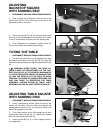
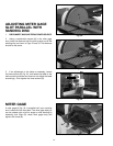
ADJUSTING MITER GAGE
SLOT PARALLEL WITH
SANDING DISC
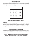
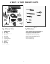
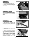
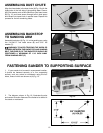
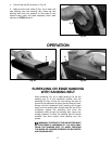
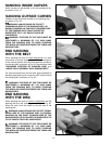
1. DISCONNECT MACHINE FROM POWER SOURCE.
2. Using a combination square (A) in the miter gage
slot, check the distance from the slot to each end of the
sanding disc, as shown in Figs. 32 and 33. This distance
should be the same.
A
A
B
B
A