


13
Fig. 28
Fig. 29
Fig. 30
Fig. 31
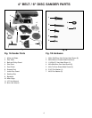
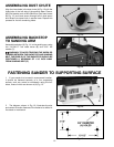
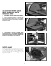
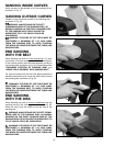
3. Place a square (B) Fig. 29, on the sanding belt with
one end of the square against the backstop, and check
to see if the backstop is square with the sanding belt.
4. If an adjustment is necessary, loosen screw (C)
Fig. 29, and adjust the backstop accordingly.
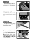
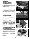
ADJUSTING
BACKSTOP SQUARE
WITH SANDING BELT
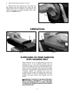
1. DISCONNECT MACHINE FROM POWER SOURCE.
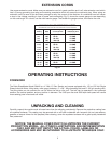
2. When making this adjustment make sure the belt
tension lever (A) Fig. 28, is all the way to the left in the
tightened position, as shown.
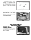
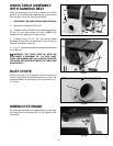
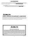
TILTING THE TABLE
1. DISCONNECT MACHINE FROM POWER SOURCE.
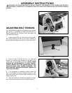
2. The table can be tilted up to 45 degrees to the right
by loosening the table lock knob (A) Fig. 30, tilting the
table to the desired angle, and tightening table lock knob
(A).
3. WARNING: AFTER TILTING, THE TABLE AS-
SEMBLY MUST BE REPOSITIONED ON THE SUP-
PORT ROD (B) FIG. 30, TO PROVIDE A MAXIMUM OF
1/16 INCH DISTANCE BETWEEN THE SANDING DISC
(C), AND THE EDGE (D) OF THE TABLE, TO AVOID
TRAPPING THE WORK OR FINGERS BETWEEN THE
DISC AND TABLE. TO REPOSITION THE TABLE
ASSEMBLY, LOOSEN SCREW (E), MOVE TABLE
ASSEMBLY ON ROD (B), AND TIGHTEN SCREW (E).
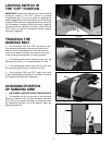
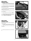
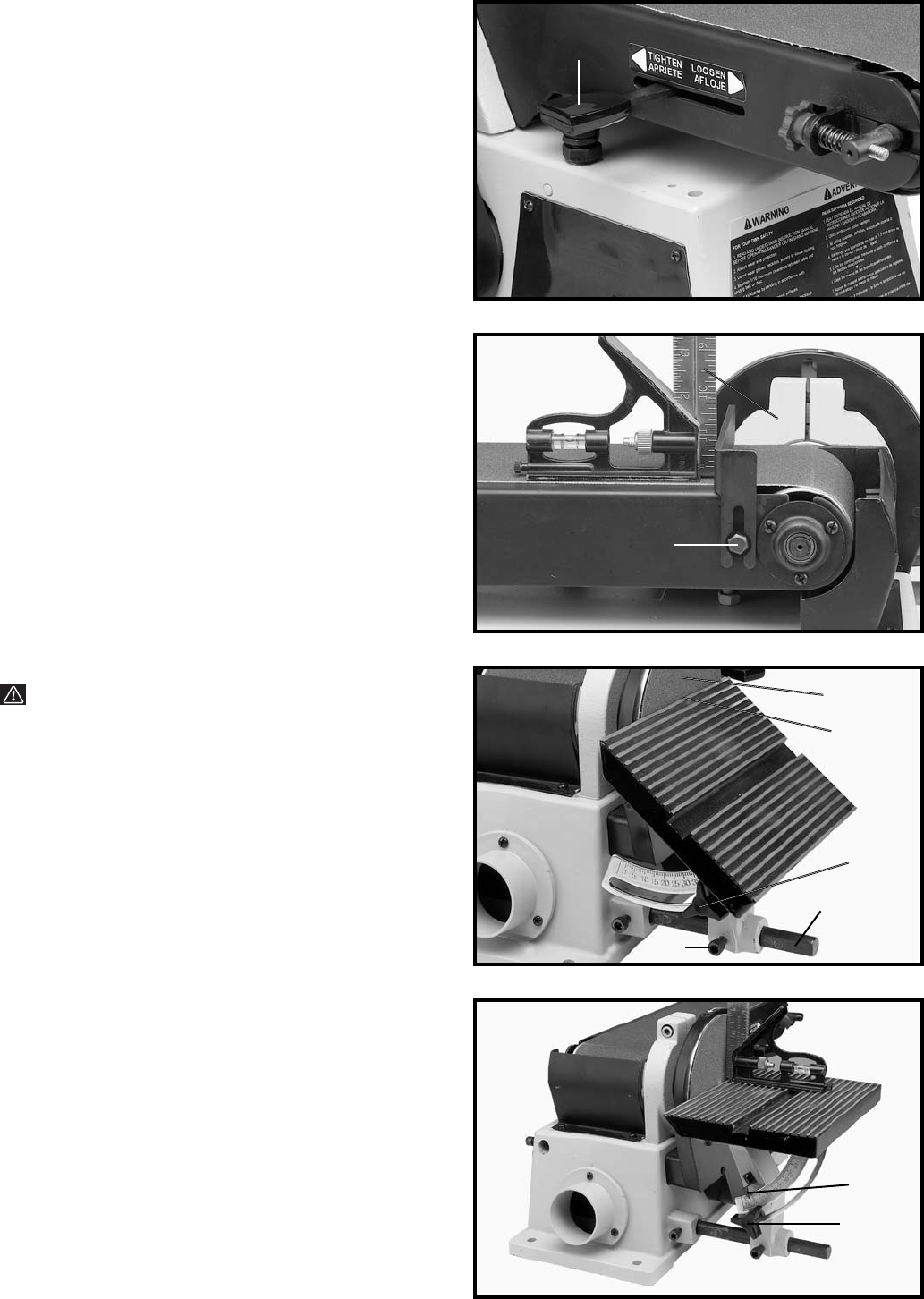
ADJUSTING TABLE SQUARE
WITH SANDING DISC
1. DISCONNECT MACHINE FROM POWER SOURCE.
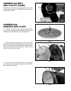
2. Using a combination square, place one end of the
square on the table with the other end against the
sanding disc, as shown in Fig. 31, and check to see if the
table is 90 degrees to the disc.
3. If the table surface is not 90 degrees to the disc,
loosen table lock knob (A) Fig. 31, adjust table square
with disc and tighten lock knob (A).
4. Adjust pointer (B) Fig. 31, to the 0 degree mark on
the angle scale.
A
C
B
B
E
A
D
C
A
B