


8
Fig. 8
Fig. 6
Fig. 7
Fig. 5
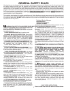
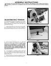
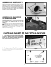
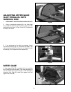
ASSEMBLING BELT
AND PULLEY GUARD
Assemble the belt and pulley guard (A) Fig. 5, to the
machine base using the two M6x1x30mm cheese head
screws (B), as shown.
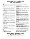
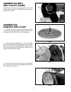
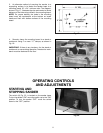
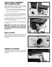
ASSEMBLING
SANDING DISC PLATE
1. Back the 1/4-20x1/4" hex socket set screw (A) Fig.
6, out of the hole, just enough so that the set screw is not
extending into hole (B) Fig. 6, in the sanding plate.
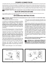
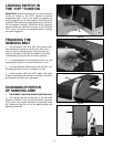
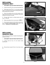
2. Slide sanding disc plate (B) Fig. 7, on drive shaft (C)
making sure flat on drive shaft is aligned with set screw
(A) in hub of plate (B). Slide plate (B) onto shaft (C) until
plate surface and shaft are nearly flush. Shaft must not
extend out past surface of plate.
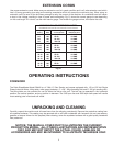
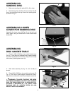
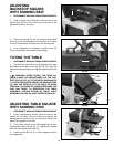
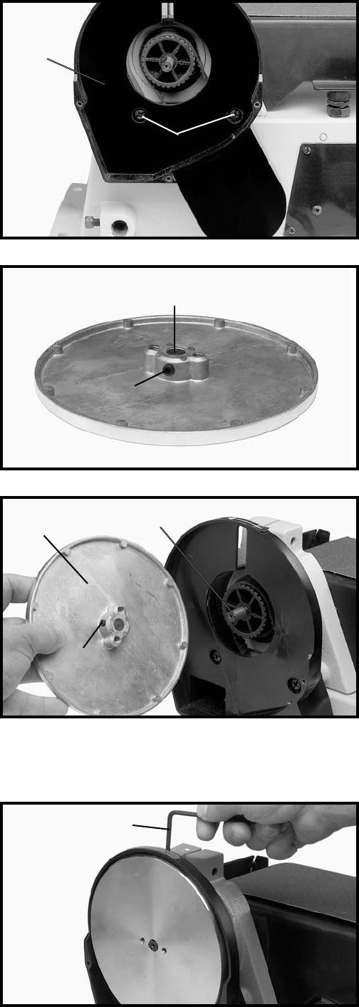
3. Insert the 1/8" hex wrench (D) Fig. 8, down through
slot in the back of belt and pulley guard and tighten set
screw against flat on shaft.
B
A
A
A
B
C
B
D