


11
Fig. 18
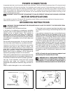
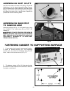
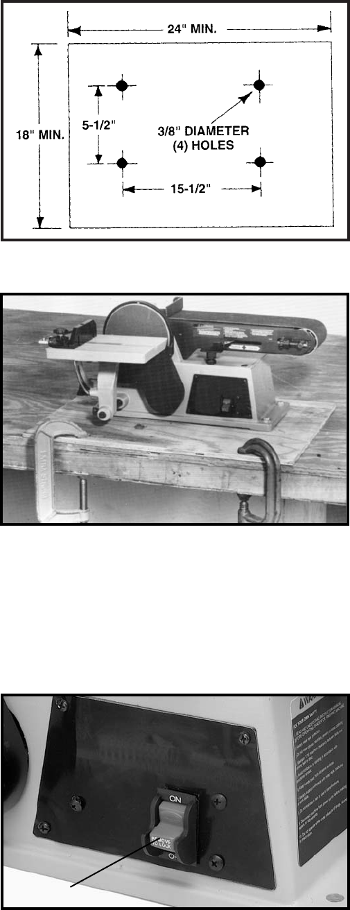
3. An alternate method of securing the sander to a
supporting surface is to fasten the sander base to a
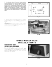
mounting board 18" x 24" minimum size. The diagram,
shown in Fig. 17, illustrates the size and center to center
distance of the holes to be drilled in the mounting board.
NOTE: For proper stability, the holes in the mounting
board must be countersunk at the bottom so screw
heads are flush with bottom surface of the mounting
board.
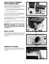
4. Securely clamp the mounting board to a stand or
workbench using 2 or more “‘C” clamps, as shown in
Fig. 18.
IMPORTANT: If there is any tendency for the stand or
workbench to move during operation, the stand or work-
bench must be fastened to the floor.
Fig. 17
OPERATING CONTROLS
AND ADJUSTMENTS
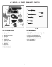
Fig. 22
STARTING AND
STOPPING SANDER
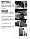
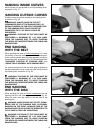
The switch (A) Fig. 22, is located on the sander base.
To turn the sander “ON” move the switch up to the “ON”
position. To turn the sander “OFF” move the switch
down to the “OFF” position.
A