


15
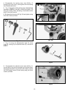
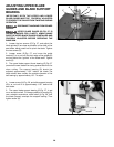
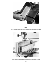
ADJUSTING LOWER BLADE
GUIDES AND BLADE SUPPORT
BEARING
The lower blade guides and blade support bearing
should be adjusted at the same time as the upper guides
and support bearings as follows:
DISCONNECT MACHINE FROM POWER
SOURCE.
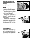
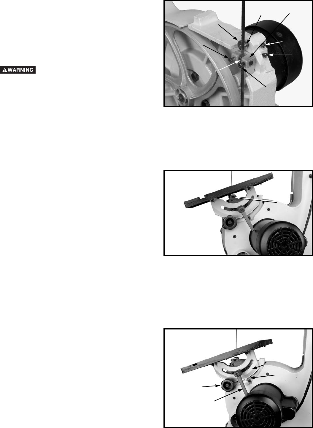
1. Loosen two screws (A) Fig. 29, and move guides (B)
as close as possible to the sides of the blade. Be careful
not to pinch the blade. Tighten the two screws (A).
NOTE: In Fig. 29, the table has been removed for clarity.
2. The front edge of the blade guides (B) Fig. 29 should
be adjusted so they are just behind the “gullets” of the
blade teeth. Loosen screw (C), and move the assembly
(D) in or out as necessary. Tighten screw (C).
3. The lower blade support thrust bearing (E) Fig. 29
prevents the saw blade from being pushed back too far
during cutting. The support bearing should be adjusted
approximately 1/32" behind the blade. Loosen screw (F)
Fig. 29, and move the bearing shaft (G) in or out as
necessary. Tighten screw (F).
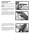
4. The lower blade support bearing (E) Fig. 29 should
also be adjusted so that the blade overlaps the outside
diameter of the ball bearing by approximately 1/8". The
blade support bearing (E) is set on an eccentric shaft.To
change the position of the bearing (E), loosen the screw
(F) Fig. 29 and rotate the shaft (G) Fig 30 until the blade
properly overlaps the support bearing. Tighten screw (F)
Fig. 29.
Fig. 29
Fig. 30
G
F
E
C
A
A
B
Fig. 31
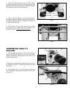
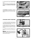
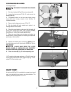
TILTING THE TABLE
The table can be tilted 45 degrees to the right. To tilt the
table, loosen lock handle (A) Fig. 31 and turn knob (B)
clockwise until desired angle is established. Then
tighten lock handle (A). NOTE: The table lock handle (A)
can be repositioned by pulling out on the handle and
repositioning it on the nut located underneath the hub of
the handle. A scale (C) and pointer (D) are provided to
indicate the degree of tilt.
A
D
C
B
D
G