9
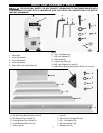
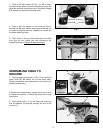
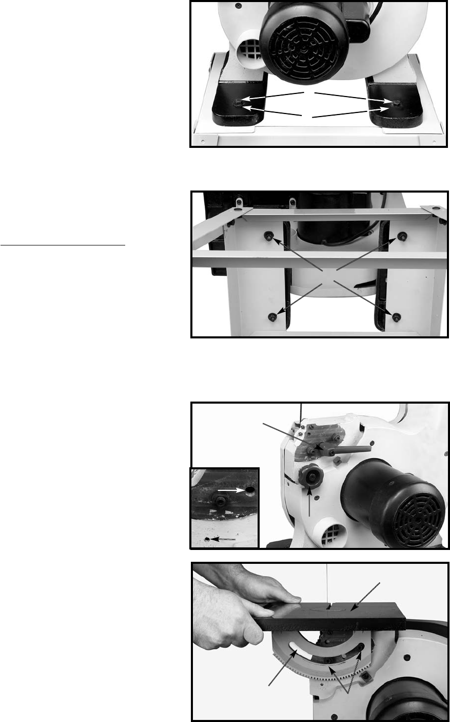
3. Place a 3/8" flat washer (H) Fig. 7 on M8 x 45mm
hex head screw. Insert the screw through the hole in the
band saw and and through the hole in the stand. Repeat
this process for the three remaining holes.
Fig. 7
D
Fig. 8
4. Place a 3/8" flat washer on the screw (D) Fig. 8,
followed by M8 lock washer, then thread a M8 hex nut
on screw and tighten securely. Repeat this process for
the three remaining holes.
5. Push down on the top of the band saw, and make
sure that all four stand feet are contacting the
supporting surface. Tighten all stand har
dware.
F
H
ASSEMBLING TABLE TO
MACHINE
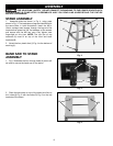
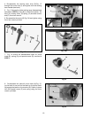
1. Remove table locking lever (A) Fig. 10 and table tilt
pinion knob (B). Be careful not to lose these parts.
(These components were assembled at the factory for
transit purposes only).
2. Remove the keeper screw, washer and wing nut from
the table slot (see Fig. 17 detail). Be careful not to lose
these parts.
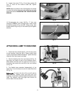
3. Place table (H) Fig. 11 on the band saw frame so
that the keepers (K) protrude through the slot of the
trunnion (L).
Fig. 10
Fig. 11
L
K
H
A
B
B
A


