


4
English
To return the circuit to setting 1, press the Bump Sensor SET Button
(C) once again. The ON LED Light (D) will shut off indicating that the
laser is in operating mode 1.
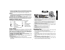
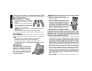
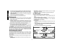
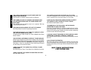
Mounting On a Tripod
1. Position the tripod on a smooth and
level surface. Set tripod to desired
height.
2. Secure the laser to the tripod base by
screwing the threaded knob (A) on the
tripod into the 5/8" x 11 threads on the
bottom and rear of the laser.
NOTE: Be sure the tripod you are working with has a 5/8" x 11
threaded screw.
3. Follow the instructions for leveling or plumbing the laser.
4. Turn the laser on; adjust rotation speed and controls as needed.
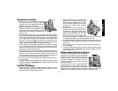
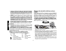
Floor Mount
The laser level can be positioned directly on the floor for leveling and
plumbing applications. Follow the instructions below for using the floor
mount.
1. Place the laser on a relatively smooth and level surface
2. Position the laser head for a level or plumb setting.
3. Follow the instructions for leveling or plumbing the laser.
4. Turn the laser on if not on already; adjust rotation speed and con-
trols as needed.
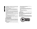
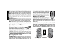
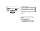
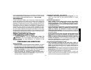
Wall Mount
The DW071 Rotary Laser has been
designed to work with an accessory
Wall Mount for attaching the tool to wall
track to aid in acoustical ceiling installa-
tion and other specialty leveling pro-
jects. Follow the instructions below for
using the Wall Mount.
A
CAUTION: Before attaching the laser level to wall track ensure that
the track is properly secured to the wall.
1. Attach the Laser to the accessory wall
mount as shown.
2. With the Wall Mount Measuring Scale fac-
ing you, rotate the Wall Mount Clamp
Locking Knob (A) towards you to open the
clamp jaws. Position the clamp jaws around
the wall track and rotate the Wall Mount
Clamp Locking Knob away from you to
close the clamp jaws shut on the track.
Ensure that the Wall Mount Clamp Locking
Knob is securely locked before proceeding.
CAUTION: Always use a ceiling wire hanger or equivalent material,
in addition to the wall mount clamp, to help secure the laser level while
mounting it to a wall. Thread the wire through the handle/roll cage.
Additionally, screws or nails can be used to fasten the tool directly to
the wall as a back up. Screw/Nail holes (B) are located in the Base
Plate next to the Base Plate Measuring Scales.
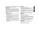
3. The tool can be adjusted up and down to the desired offset height
for working. To change the height, loosen the Rack 'N Pinion
Locking Knob (D) located on the left of the wall mount.
TIP:
You
may need to support the weight of the tool while the Rack 'N
Pinion Locking Knob is loosened. Turn the Rack 'N Pinion
Adjustment Knob (C) located to the right of the wall mount to move
the laser level up and down to set your height. Use the wall mount
Measuring Scale to pinpoint your mark.
TIP:
It may be helpful to
turn the power ON and spin the rotary head to set your height.
Once you have positioned the laser at your desired offset height,
tighten the Rack 'N Pinion Locking Knob to maintain your mark.
4. Follow the instructions for leveling the laser.
TIP:
Remember the
front leveling knob controls the movement of the bubble in the
front vial, the side leveling knob controls the movement of the bub-
ble in the side vial.
5. Turn the laser on if not on already; adjust rotation speed and con-
trols as needed.
A
B
D
C