


Electrical Connection
Be sure your power supply agrees with the nameplate
marking. AC ONLY means that your saw will operate on
alternating current only. A voltage decrease of 10 percent or
more will cause a loss of power and overheating. All D
EWALT
tools are factory tested. If this tool does not operate, check the
power supply.
Unpacking Your Saw
Your DW708 Miter Saw is assembled before it is packed in
the carton. Parts packed with your saw include:
1. One 60 tooth D
EWALT 12" (305mm) diameter saw blade
3. One blade wrench in wrench pocket shown in Figure 3
4. One base stabilizer
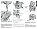
Familiarization
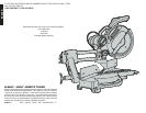
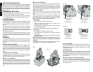
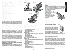
Your sliding compound miter saw is fully assembled, except
for the stabilizer, in the carton. Open the box and lift the saw
out by the lifting handle and the rail, as shown in Figure 1
and 1A.
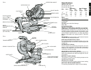
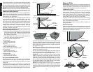
Place the saw on a smooth, flat surface such as a workbench
or strong table. Examine figures 3 & 4 to become familiar
with the saw and its various parts. The following section on
adjustments will refer to these terms and you must know what
and where the parts are.
Press down lightly on the operating handle and pull out the
lock down pin, shown in figure 3. Gently release the down-
ward pressure on the handle and allow the arm to rise to its
full height.
Controls
Your sliding compound miter saw has several main controls,
which will be discussed briefly here. For more information on
these controls, see the respective sections later in the
manual.
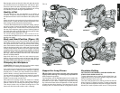
MITER CONTROL (FIGURE 3)
The miter adjustment/lock handle and detent trigger allows
you to miter your saw 50° left and 60° right. To miter the saw,
lift the miter adjustment/lock handle, squeeze the detent
trigger and set the miter angle desired on the miter scale.
Push down on the miter lock lever to lock the saw table in
place.
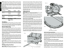
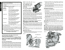
TRIGGER SWITCH (FIGURE 4)
The trigger switch turns your saw on and off. It can be used
with either hand. You can lock the saw off by placing a
padlock in the hole provided in the trigger switch.
BEVEL LOCK (FIGURE 3)
The bevel adjustment/lock handle allows you to bevel your
saw 45° left or right. To loosen the lever and adjust the bevel
setting, turn the handle counterclockwise, the saw head
bevels easily to the left. To tighten, turn the handle clockwise.
Bevel degree markings are on the bottom rear of the saw
arm.
BEVEL STOP OVERRIDE
Some models include a bevel stop override button that
allows you to override the built-in bevel stop at 0˚. The saw
will automatically stop at 0˚ when brought up from the left.
To move past 0˚ to the right, press the bevel stop override.
The saw will automatically stop at 45˚ on the left or right.
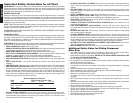
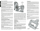
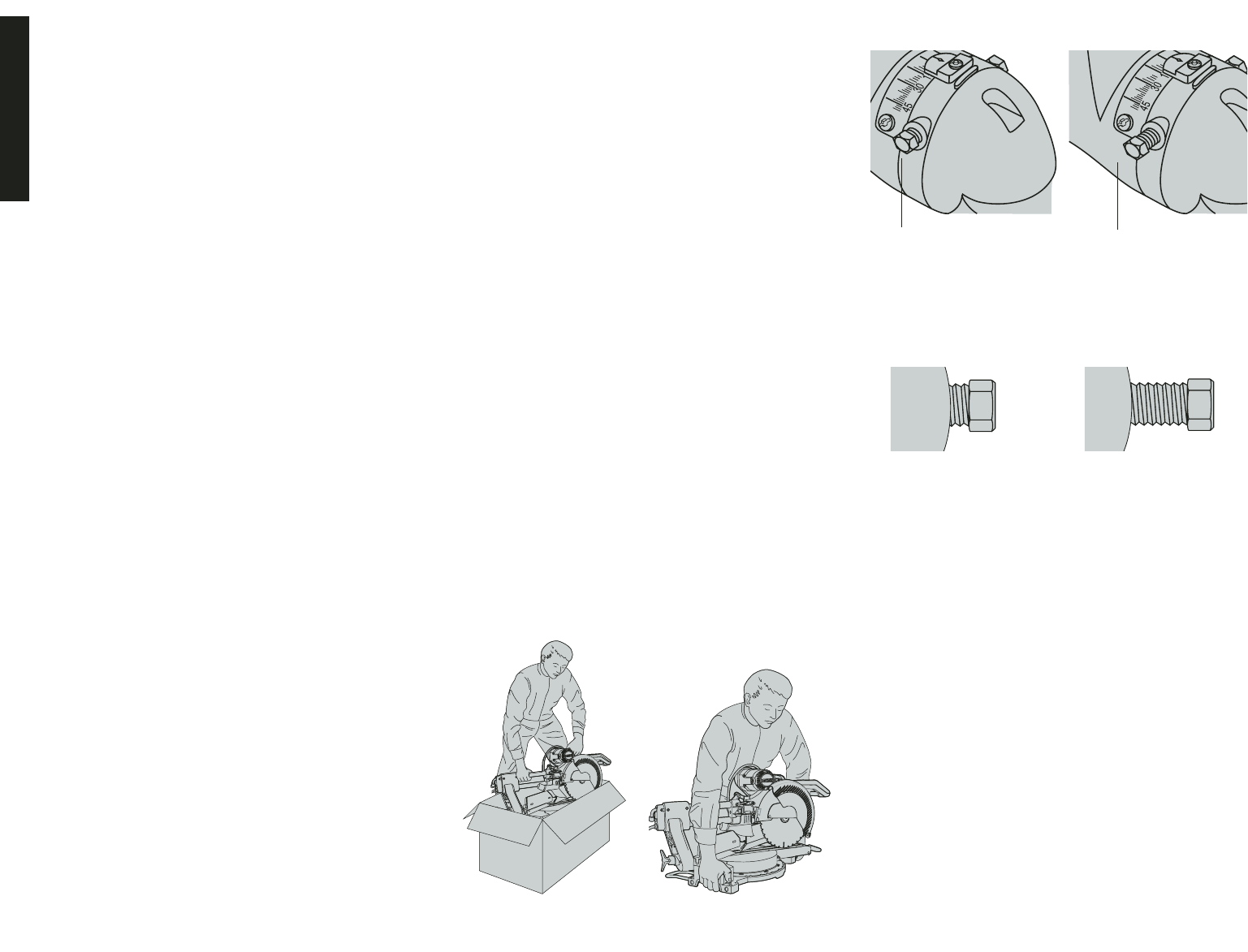
BEVEL STOP PINS
Some models include bevel stop pins (Figure 2A and 2B)
allow you to override built-in bevel stops at 0° and 45° left and
right.
Each bevel stop pin has two positions: engaged and
disengaged. When the 0° (middle) bevel stop pin is engaged,
the saw will stop at 0° when brought up from the left. To move
past 0° to the right, disengage the bevel stop pin.
To disengage:
• Bevel the saw at least 5° away from stop
• Push the stop pin in completely and rotate it 90°
counterclockwise until it stops.
• Release the bevel stop pin and allow it to spring outward
to its disengaged position.
To reset the 0° bevel stop, re-engage the bevel stop pin.
To re-engage:
• Bevel the saw at least 5° away from stop
• Push the stop pin in completely and rotate it 90° clockwise
until it stops.
• Release bevel stop pin and allow it to spring outward to its
engaged position.
NOTE: Saw will not adjust from a right bevel position to a
left bevel position with the 0° (middle) bevel stop pin
engaged.
The bevel stop pins at 45° left and right stop position can be
disengaged to 48° following the procedure above.
English
RAIL LOCK KNOB
The rail lock knob shown in figure 4 allows you to lock the saw
head firmly to keep it from sliding on the rails. This is
necessary when making certain adjustments or when
transporting the saw.
GROOVING STOP
The grooving stop shown in figure 4 allows for groove cutting.
Flipping the grooving lever toward the front of the saw and
adjusting the thumbscrew changes the depth of the groove
cut. Flipping the lever toward the rear of the saw bypasses the
grooving stop.
MOVABLE FENCE ADJUSTMENT KNOBS
The fence adjustment knobs allow adjustment of the left or
right fence. Loosen the plastic adjustment knob (behind the
fence) and slide the fence in or out. Retighten before
operating the saw.
FIG. 1
FIG. 1A
FIG.2A
FIG. 2B
BEVEL STOP PIN:
ENGAGED
BEVEL STOP PIN:
DISENGAGED
BEVEL STOP:
ENGAGED
BEVEL STOP:
DISENGAGED
4
SOME MODELS
SOME MODELS
SOME MODELS
SOME MODELS