


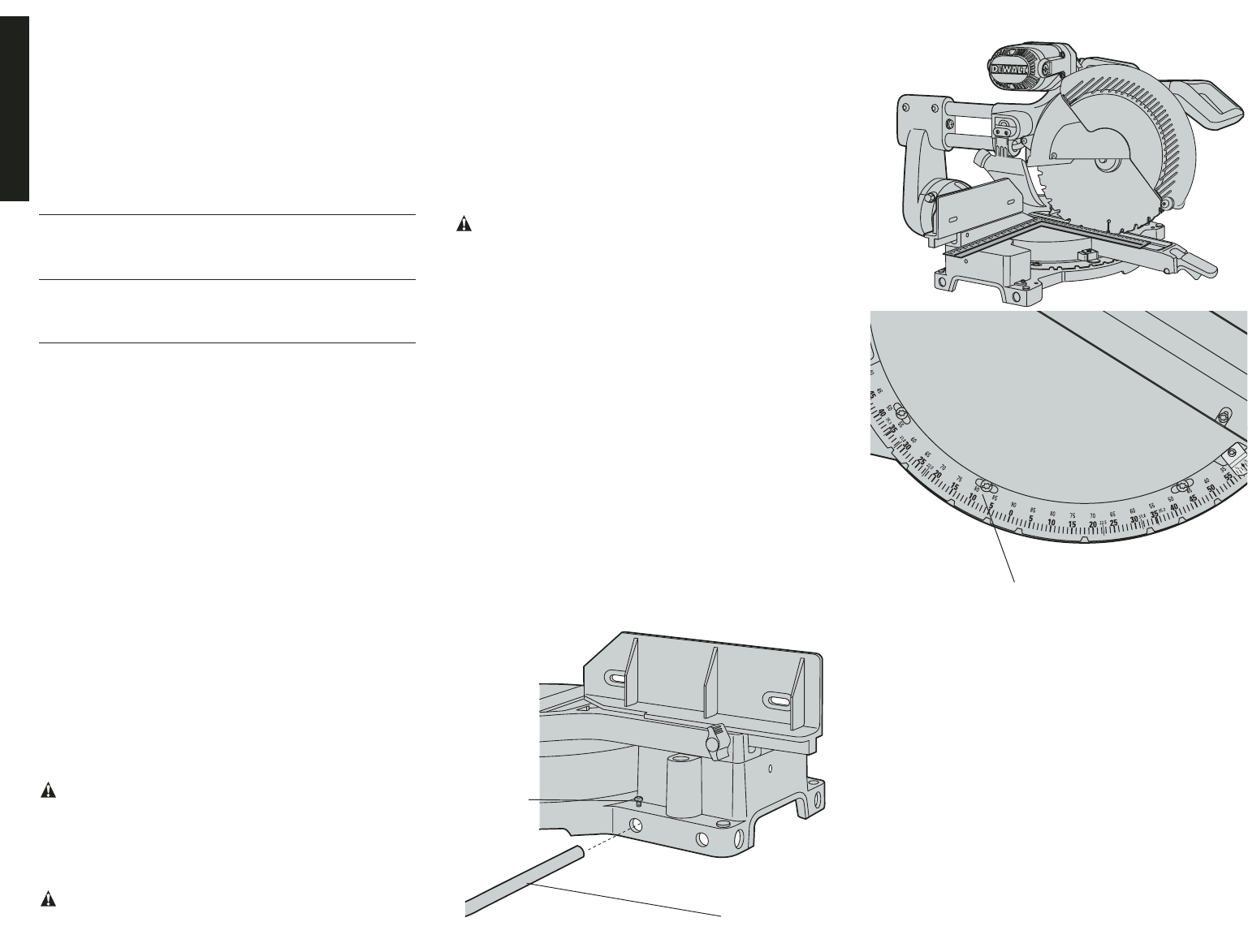
FIG. 5
STABILIZER
SCREW
BACK OF SAW
6
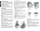
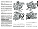
NOTE: Spout has a provision to attach a vacuum hose to
collect sawdust. Proper orientation of dust bag is necessary
to avoid interference during operation of saw. If interference
cannot be avoided, dust bag must be removed. ALWAYS
MAKE A DRY RUN WITHOUT POWER BEFORE MAKING
ANY CUTS.
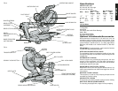
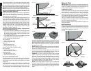
SAW BLADES: ALWAYS USE 12" (305mm) SAW BLADES.
SPEED RATING MUST BE AT LEAST 4800 RPM. USE OF
SMALLER DIAMETER BLADES MAY CAUSE SEVERE
DAMAGE TO SAW.
Application Blade No. of Type
Descript. Teeth of Cut
Fine Trim Precision 60-100 Very
Molding Ground Smooth
Carbide Splinter
Free
Trim, Framing, Combination 32-60 Smooth
Pressure Multi-Purpose Fast Cut
Treated
Decking
Aluminum Non-Ferrous 60-80 —
Metal Cutting
Negative Rake
Teeth
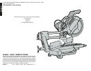
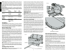
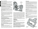
Stabilizer
Your saw includes one base stabilizer. This must be installed
before using your saw. Insert the stabilizer into the holes in
the back of the unit, as shown in figure 5. Move the stabilizer
in or out until it contacts the work surface. Then tighten the
screws in the base to fasten the stabilizer.
Bench Mounting
Holes are provided to facilitate bench mounting, as shown in
figure 4. (Two different sized holes are provided to
accommodate different sizes of screws. Use either hole, it is
not necessary to use both.) Always mount your saw firmly to
prevent movement. To enhance the tool’s portability, it can be
mounted to a piece of 1/2" (12.7mm) or thicker plywood which
can then be clamped to your work support or moved to other
job sites and reclamped.
NOTE: If you elect to mount your saw to a piece of plywood,
make sure that the mounting screws don’t protrude from the
bottom of the wood. The plywood must sit flush on the work
support. When clamping the saw to any work surface, clamp
only on the clamping bosses where the mounting screw holes
are located. Clamping at any other point will interfere with the
proper operation of the saw.
CAUTION: To prevent binding and inaccuracy, be sure
the mounting surface is not warped or otherwise uneven. If
the saw rocks on the surface place a thin piece of material
under one saw foot so that the saw sits firmly on the mounting
surface.
Transporting the Saw
CAUTION: Disconnect the saw from the power supply
before moving it or making any adjustments.
English
FIG. 6
FIG. 7
MITER SCALE SCREW
Use the lock down pin shown in figure 4 when carrying the
saw from one place to another. The lock down pin is not to
be used for any cutting operation, and is for carrying and
storage only. When transporting the saw, always lock the
head in the down position, miter the saw fully to the right
(60° miter), lock the miter adjustment/lock handle, lock the
rail lock knob with the head fully forward, slide the fences
completely inward, and lock the bevel adjustment/lock
handle with the saw at a 0° bevel. Always use the carrying
hand holds in the base to transport the saw. Carry the saw
as shown in figure 1A.
Adjustments
CAUTION: Disconnect the saw from the power supply
before moving it or making any adjustments.
NOTE: Your sliding compound miter saw is fully and accu-
rately adjusted at the factory at the time of manufacture. If
readjustment due to shipping and handling or any other
reason is required, follow the steps below to adjust your saw.
Once made, these adjustments should remain accurate.
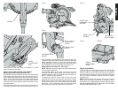
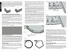
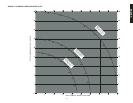
MITER SCALE ADJUSTMENT
Place a square against the saw’s base, fence and blade, as
shown in figure 6. Do not touch the tips of the blade teeth
with the square because this will cause an inaccurate
measurement. Lift the miter clamp handle and swing the miter
arm until the miter latch locks it at the 0 miter position. Check
that the saw blade is exactly perpendicular (square) to the
fence. You will know the blade is perpendicular to the fence
when no gap is visible between the blade and the square or
the fence and the square.
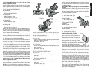
If the saw blade is not exactly perpendicular to the fence,
loosen the four screws that hold the miter scale to the base
shown in figure 7 and move the scale/miter arm assembly
left or right until the blade is perpendicular to the fence, as
measured with the square. Retighten the four screws. Pay
no attention to the reading of the miter pointer at this time.
MITER POINTER ADJUSTMENT
Lift the miter adjustment/lock handle and move the miter arm
to the zero position, as shown in figure 8. With the miter
adjustment/lock handle loose allow the miter latch to snap into
place as you rotate the miter arm to zero. Observe the pointer
and miter scale. If the pointer does not indicate exactly zero,
loosen the screw that holds the pointer in place and gently
move the pointer left or right. Retighten the screw after setting
the pointer to zero.
MITER LOCK/DETENT ROD ADJUSTMENT
The miter lock/detent rod should be adjusted if the table of the
saw can be moved when the miter adjustment/lock handle is
locked down.
To adjust the miter lock/detent rod, put the miter adjust-
ment/lock handle in the up, unlocked position. Using a slotted
screwdriver, tighten the lock rod by turning it clockwise as
shown in figure 9. Turn the lock rod until it is tight, then turn
counterclockwise 1/4 turn. To ensure the lock handle is
functioning properly, re-lock the miter lock to a non-detented