


10
© 2012 Emerson Climate Technologies, Inc.
Printed in the U.S.A.
AE4-1395
Application Engineering
BULLETIN
SERVICE PROCEDURES
Modulation Troubleshooting
The modulation valve and solenoid coil are engineered
forspecicusewiththedigitalscroll.Don’tattemptto
substitute replacement solenoid coils that are not of
the correct part number. The 3 to 7.5 ton modulation
valves must be installed in the correct orientation and
with the arrow on the valve pointing to suction. Installing
a modulation valve in a horizontal position, or with the
suction and discharge connections reversed, can result
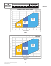
in sporadic operation of the modulation valve. See
Figure 8 for an illustration of the correct valve location
and orientation.
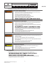
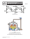
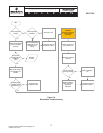
Figure 10isatroubleshootingowcharttohelpwith
simple modulation problems. For more information on
troubleshooting the Copeland
™
Digital Compressor
Controller please refer to AE8-1328. For more
information on troubleshooting the Emerson Commercial
Comfort Controller please refer to AE8-1393.
3 to 7.5 Ton Modulation Valve Replacement
Procedure
The 3 through 7.5 ton digital scroll compressors employ
a modulation valve that is mounted external to the
compressor in the modulation tubing. To replace the
modulation valve, follow these recommended steps:
1. Disconnect and lockout the power to the unit.
2. Recover the refrigerant charge from the compressor/
system.
3. Remove the screw holding the coil to the valve
using a Phillips screwdriver or appropriate size nut
driver.
4. Remove the coil from the valve.
5. Using manifold gauges, double check to make
sure the refrigerant charge is completely
recovered from the compressor before
proceeding.
6. Using tubing cutters, cut the modulation tubing
close to the valve body leaving the valve tubing
stubs in the suction “T” connection and the swaged
tubing from the compressor top cap.
7. Carefully unbraze and remove the tubing stubs from
the suction “T” and top cap tubing swage. Carefully
unbrazing and removing these stubs will allow the
tubing/suction“T”ttingtobereused.
8. Afterthesettingshavecooled,cleanthettings
and prepare to braze the new valve in place. Wrap
a wet rag around the valve body to keep from
overheating the valve.
9. Using standard brazing practices for refrigeration
systems, carefully braze the new valve into the
system, directingthe torchame awayfrom the
valve body.
10. Check for leaks using nitrogen with a properly sized
regulating and relief valve.
11. Install the solenoid coil and torque the retaining
screw to 25 in-lbs.
12. Evacuate the compressor/system and put the
system back into operation.
8 To 15 Ton Modulation Valve Replacement
Procedure
The 8 through 15 ton digital scroll compressors have
a modulation valve that is replaceable in the event the
valve stops functioning. The modulation valve threads
into a receptacle that is inside the small terminal box on
the compressor. To replace the modulation valve, follow
these recommended steps:
1. Disconnect and lockout the power to the unit.
2. Recover the refrigerant charge from the compressor/
system.
3. Remove the cover from the small terminal box and
remove the screw holding the coil to the valve using
a Phillips screwdriver or appropriate size nut driver.
4. Remove the coil from the valve and clean the area
around the valve body to prevent debris and dirt
from entering the system when changing the valve.
5. Using manifold gauges, double check to make
sure the refrigerant charge is completely
recovered from the compressor before
proceeding.
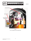
6. Using a 7/8” deep well socket and ratchet, turn the
valve counterclockwise to remove the valve.
7. Visually inspect the valve receptacle on the
compressor for damage or debris. Ensure that the
blacko-ringandwhiteTeongasketareremoved
with the valve and do not remain on the valve
receptacle.
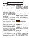
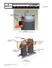
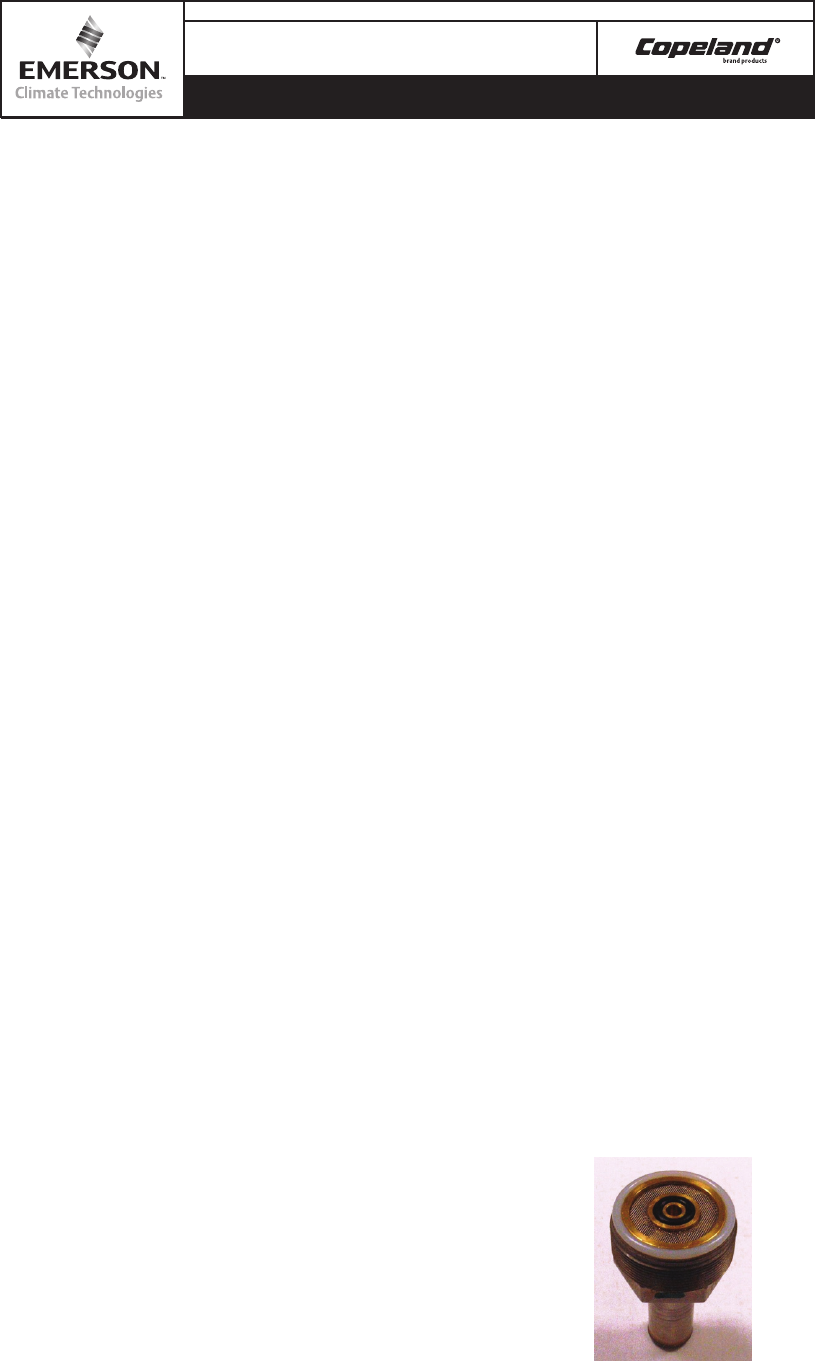
8. The replacement valve should have a new,
black o-ringand white,Teongasket as shown: