


4
© 2012 Emerson Climate Technologies, Inc.
Printed in the U.S.A.
AE4-1395
Application Engineering
BULLETIN
Introduction
The 3 to 15 ton Copeland Scroll Digital
™
compressors
described in this bulletin include the follow compressor
model numbers:
R-410A R-22 & R-407C
ZPD34 to ZPD54K5 ZRD36 to ZRD81KC
ZPD61 to ZPD91KC ZRD94 to ZRD125KC
ZPD103 to ZPD182KC
ZPD and ZRD digital scroll compressors are variable
capacity compressors that can modulate down to 10%
of full load. Digital scrolls are suitable for a variety of
applications where a variable capacity compressor is
useful, such as VAV applications, dedicated outside
air units, units that typically used hot gas bypass for
capacity control, and applications that require accurate
control of temperature and humidity. Other applications
include multiple compressor systems where modulation
is required over the entire operating range of the system
and in applications where compressor starting and
stopping is unacceptable. Typical digital scroll model
numbers are ZRD94KCE-TF5 and ZPD182KCE-TWD.
This bulletin describes the operating and application
differences with respect to the equivalent fixed
capacity Copeland Scroll
™
compressors. The following
Application Engineering bulletins should be consulted
for non-modulating scroll application guidelines:
AE4-1331 1.5 to 5 Ton R-410A
AE4-1365 5 to 7.5 Ton R-410A
AE4-1303 8 to 15 Ton R-22, R-407C & R-410A
AE4-1312 1.5 to 7 Ton R-22 & R-407C
Nomenclature
The model number of the Copeland Scroll Digital
compressors includes the approximate nominal
60 Hz capacity at the AHRI high temperature full
load air conditioning rating point. An example is the
ZPD120KCE-TFD, which has approximately 120,000
Btu/hr cooling capacity at the air conditioning rating
point when operated on 60 Hz. Note that the same
compressor will have approximately 5/6 of this capacity
or 100,000 Btu/hr when operated on 50 Hz power.
Please refer to the Online Product Information at
www.EmersonClimate.com for more information on
performance at part load.
Digital Compressor Operation
The digital scroll is capable of seamlessly modulating
its capacity from 10% to 100%. A normally closed
(de-energized) solenoid valve is a key component for
achieving modulation. When the solenoid valve is in its
normally closed position, the compressor operates at
full capacity, or loaded state. When the solenoid valve
is energized, the two scroll elements move apart axially,
or into the unloaded state. During the unloaded state,
the compressor motor continues running, but since
the scrolls are separated, there is no compression.
During the loaded state, the compressor delivers 100%
capacity and during the unloaded state, the compressor
delivers 0% capacity. A cycle consists of one loaded
state and one unloaded state. By varying the time of
the loaded state and the unloaded state, an average
capacity is obtained. The lowest achievable capacity is
10% which equates to 1.5 seconds of pumping during
one 15 second cycle.
An example for the 15 second controller cycle: In any
15 second cycle, if the loaded time is 10 seconds and
the unloaded time is 5 seconds, the average capacity
is 66% or if the loaded time is 5 seconds and the
unloaded time is 10 seconds the capacity during that
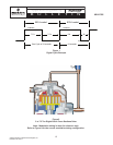
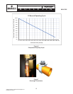
15 second period is 33%. See Figure 1 for a graphical
representation of the digital cycle, and Figure 6 for
a graph showing solenoid on-time vs. compressor
capacity.
How it Works
The digital scroll compressor unloads by taking
advantage of the Copeland Scroll
compressor's
axial compliance. All Copeland Scroll compressors
are designed so that the compression elements can
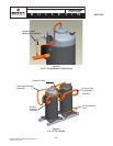
separate axially a few thousands of an inch. The 3
through 7.5 ton compressors described in this bulletin
use a lift piston mechanism to separate the scrolls during
the unloaded state. When the solenoid is energized the
volume on top of the piston is vented to the low side
allowingthepistonandxedscrollassemblytomove
axial away from the orbiting scroll. When the solenoid is
de-energized the piston is forced down and the scrolls
are loaded axially.
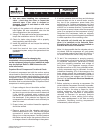
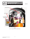
The 8 ton and larger digital scroll compressors employ
a solenoid valve that is mounted on the side of the
compressor that vents the intermediate cavity to the
low side of the compressor during the unloaded state.
During the loaded state the solenoid valve is de-
energized and the intermediate cavity is pressurized
toloadtheoatingsealandscrollsaxially.
Please refer to Figures 2 and 3 for cross sectional
pictures of the two digital modulation mechanisms.
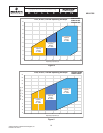
APPLICATION CONSIDERATIONS
Operating Envelope
The operating envelope of the digital scroll compressors
for all loading conditions is shown in Figures 4 and 5.