


9
© 2012 Emerson Climate Technologies, Inc.
Printed in the U.S.A.
AE4-1395
Application Engineering
BULLETIN
7. Using the appropriate lifting devices, carefully
remove the compressor from the system.
The following steps should be followed to install the digital
compressor into the system.
1. Before removing the rubber plugs, install the
compressor in the unit on the mounting grommets
using the appropriate lifting devices.
2. Install the compressor mounting bolts.
3. Connect the suction and discharge lines using
standard brazing practices.
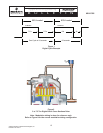
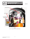
4. If the compressor has an external modulation valve
and tubing (3 to 7.5 ton only) refer to Figure 8 for the
correct valve orientation and position. Wrap a wet
rag around the valve and complete the assembly
by brazing the valve and tubing into place.
5. Check for leaks using nitrogen with a properly sized
regulating and relief valve.
6. Connect conduits and wiring to the compressor.
Inspect and/or replace the contactor. If the
compressor is 1-phase, install the correct run
capacitor.
NOTICE
The above procedures for changing the
compressor are not comprehensive and additional
steps/procedures may be necessary.
Refrigerant Flow Control
In the system with a digital compressor, the refrigerant
owcontrolvalveisrequiredtocontrolowacrossawide
rangeofowratesandvaryingpressuredifferentials.
Most balanced port thermostatic expansion valves can
controlowdowntoabout40%oftheirratedcapacity.
Excessive hunting and loss of superheat control can
result when asking a thermostatic expansion valve to
operate outside of its design range. For this reason,
the expansion device needs to be evaluated to ensure
reliable operation over the expected operating range.
Limiting the minimum compressor modulation rate to
a value that the expansion valve can tolerate should
be considered. Electronic expansion valves should be
considered if modulation over the entire range of the
compressor’s modulation range is anticipated.
Evaporator Air Flow
For the highest level of energy savings, comfort, and
efciencythevariablecapacitysystemshouldbecapable
of varyingthe airow. Variable frequencydrives and
tapped blowers are two means of reducing air ow.
Reducing air ow in humid or maritime climates is
important to maintain coil temperatures low enough to
remove latent heat. In desert and arid climates, because
oflowornolatentloads,airowislesscritical.
Thecontrolsrequiredforvariableairowarenotprovided
by Emerson so the contractor may need to consult with
controlsexpertsinthiseld.
Condenser Air Flow
Modulatingthecondenserairowisnotcriticaltothe
success of the application. For the highest level of energy
savings,condenserairowwillbereducedbasedonthe
compressor modulation rate, condensing temperature,
ambient temperature, etc.
Modulation Control
Thepreferredmodulationcontrolforretrotapplications
is the Commercial Comfort Controller. This controller is a
closed loop controller that is installed in the conditioned
space. The controller measures the space temperature
and through an algorithm in the controller, controls the
modulation of the digital scroll. The controller can be
positioned up to 300 feet from the compressor/unit, is
congurableforrooftopunitorheatpump,andiswired
like a commercial room thermostat. For more information
on the Commercial Comfort Controller please refer to
AE8-1393.
ASSEMBLY LINE PROCEDURES
3 To 7.5 Ton Modulation Valve Brazing Procedure
The external modulation valve is purchased and shipped
separately from the 3 to 7.5 ton digital scroll. Therefore,
assembly is required in the OEM manufacturing plant.
Figure 8 illustrates the correct position and orientation
of the modulation valve. Please note the direction of the
arrow on the valve, it must point to suction.
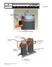
When brazing the modulation valve into the system,
the valve must be wrapped with a wet rag to help keep
thevalvecool.Thetorchamemustbedirectedaway
from the valve and the brazing operation should be
done quickly so the valve isn't overheated. The brazing
operation should be performed with a nitrogen purge to
prevent the build-up of copper oxide. The solenoid coil
should be installed after the brazing operation, so the
leads are kept away from the brazing operation and the
wet rag is able to fully contact the valve body.
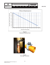
Pressure Testing
The pressure used on the OEM assembly line to meet
the UL burst pressure requirement cannot be higher
than 400 psig (27.6 bar) for R-407C & R-22 and 475
psig (32.8 bar) for R-410A. Higher pressure may result
in permanent deformation of the compressor shell and
possibly cause misalignment or bottom cover distortion.