


8
© 2012 Emerson Climate Technologies, Inc.
Printed in the U.S.A.
AE4-1395
Application Engineering
BULLETIN
hot-gas-bypass for capacity control are also ideal units
foradigitalscrollretrot.
Retrot Applications To Avoid
NOTICE
Always check with the original equipment
manufacturer, before modifying the equipment,
to understand their warranty policies regarding
equipment modications.
Thesuccessoftheretrotwilldependontheamount
of planning and evaluation done before the retrot.
Applications such as clean rooms for manufacturing
sensitive components, laboratories, hospital operating
and recovery rooms, and equipment rooms that require
constantcoolingareallapplicationsthatwouldbenet
from a modulating digital scroll. Many of these are
critical cooling applications and require equipment that
is designed specically for these applications. Don’t
attempt to retrot a non-modulating HVAC unit, in a
critical application, to one with a digital scroll in an attempt
to make the unit perform well beyond its intended use.
Applications that have complex refrigeration circuits
(modulating reheat, heat recovery for water heating,
etc.)shouldnotbeconsideredforadigitalscrollretrot.
Performance Modeling
NOTICE
Emerson Climate Technologies, Inc. is not
responsible or liable for incorrect energy use
predictions.
Successfuldigitalscroll retrotprojects,andresultant
energy savings, have been documented by several
industry energy groups. Predicting the energy usage
and calculating a return on investment before the
project is undertaken is not trivial and is best done by
experienced companies that use advanced software
programs to predict energy use. Before large retrot
projects are considered, as much front-end analysis
as possible should be done to better predict how much
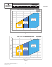
energy might be saved. Tabular performance data and
thetencoefcientsfortheAHRIpolynomialequationfor
performance at 50% and 100% load are available for
modeling purposes in the Online Product Information
(OPI) section at www.EmersonClimate.com.
System Modications
NOTICE
Always check with the OEM of the equipment
being considered for the digital scroll retrot,
before the retrot is undertaken. The OEM may
have specic instructions developed that offer
step by step guidance.
Before beginning the retrot, the system should be
operable and system operating conditions should be
logged for future reference. The compressor suction
& discharge pressures, suction superheat, subcooling,
volts,amps,evaporatorairowandleavingtemperature,
and system charge should all be measured and recorded
priortoanysystemmodications.
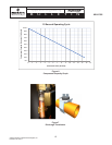
Compressor Selection & Change-Out
The replacement digital scroll compressor should be
compared to the non-modulating compressor in at least
these three areas:
1. Performance – the full load capacity of the digital
scroll should be approximately equal to the capacity
of the compressor being replaced. In some cases
in might make sense to “right size” the compressor
capacity for the load if the compressor is grossly
oversized.
2. Electrical – the digital scroll compressor RLA and
LRA should be compared to the compressor being
replaced. Contactor, wire, breaker/fuse, and run
capacitor sizes should be evaluated.
3. Mechanical – in most cases the compressor
mounting will be identical for the non-modulating
and the digital scroll. There could be minor
difference in the suction and discharge tubing
locations, as well as the height of the compressor.
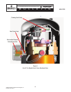
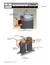
The following steps should be followed to remove the
non-modulating compressor from the system.
1. Using an EPA approved refrigerant recovery
machine, recover the system refrigerant charge
from the low and high sides of the system.
2. Disconnect and lockout the power supply.
Confirm that all voltage sources have been
disconnected by using a voltmeter. Disconnect the
conduits and wiring to the compressor and move
them out of the way as much as possible.
3. By using manifold gauges, verify that the system
refrigerant charge is completely recovered from
the system. Suction and discharge pressures must
be 0 psig.
4. Using a tubing cutter, cut the suction and discharge
lines close to the compressor.
5. Remove the compressor mounting bolts.
6. Plug the compressor suction and discharge
connections to prevent the spillage of oil from the
compressor when removing it from the system.