


www.controltechniques.com
17
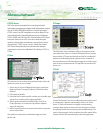
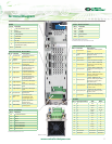
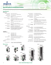
Terminal Diagram
Bottom view
Power - DC Connections
Pin # Function
48V 48Vdc
-DC
- DC Bus
+DC + DC Bus
BR Brake Resistor
GND Ground
Connection shown for size 1 unit
Terminal locations may vary based on unit size
Control Terminals - Top Row
Pin # Function Description
1 0V Common
Common for backup power
supply
2
+24Vdc External
Input
60W, 24Vdc - Backup power
supply for control
3 0V Common
Common for external analog
signals
4 10Vdc source 10mA max reference supply
5 Analog Input 1+
±10Vdc 100kΩ - differential
analog input, non-inverting
input, 16 bit
6 Analog Input 1-
±10Vdc 100kΩ - differential
analog input, inverting input,
16 bit
7 Analog Input 2
±10Vdc, 100kΩ or 0-20/
4-20mA, 200Ω single-ended
analog input 10 bit
8 Analog Input 3
±10Vdc, 100kΩ or 0-20/
4-20mA, 200Ω single-ended
analog input 10 bit, motor
thermistor input
9 Analog Output 1
±10Vdc or 0-20 / 4-20mA
single-ended analog output,
bi-polar, 10 bit
10 Analog Output 2
±10Vdc or 0-20 / 4-20mA
single-ended analog output,
bi-polar, 10 bit
11 0V Common
Common for external analog
signals
Control Terminals - Bottom Row
Pin # Function Description
21 0V Common
Common for external
digital inputs
22
+24Vdc
Output
200mA max user supply
23
0V Common
Common for external
digital inputs
24
Digital I/O 1
0 to 24Vdc input, or 1
to 24Vdc, 240mA max
output digital I/O
25
Digital I/O 2
0 to 24Vdc input, or 1
to 24Vdc, 240mA max
output digital I/O
26
Digital I/O 3
0 to 24Vdc input, or 1
to 24Vdc, 240mA max
output digital I/O
27
Digital Input 4
0 to 24Vdc, 6kΩ digital
input
28
Digital Input 5
0 to 24Vdc, 6kΩ digital
input
29
Digital Input 6
0 to 24Vdc, 6kΩ digital
input
30
0V Common
Common for external
digital inputs
31
Safe Torque
Off
0 to 24Vdc, 8µsec
typical/20µsec max
sample digital input
41
Status Relay
240Vac, 2A resistive
normally open
42
Status Relay
240Vac, 2A resistive
normally open
Power - Line/Motor
Pin # Function
PE Ground Connection
L1 Line In
L2 Line In
L3 Line In
U Motor Connection
V Motor Connection
W Motor Connection
GND Motor Ground
Connection shown for Size 1 unit
Encoder
Pin #
Signal Quadrature
ABS Pulse
1 A Cos F
2 A/ Cosref F/
3 B Sin D, R
4 B/ Sinref D/, R/
5 Z Data Z
6 Z/ Data/ Z/
7 U n/c U
8 U/ n/c U/
9 V n/c V
10 V/ n/c V/
11 W Clock W
12 W/ Clock/ W/
13 +V +V +V
14 0V Common 0V Common 0V Common
15 Thermistor Thermistor Thermistor
RS485
Pin # Function
1 120Ω Termination resistor
2 RX TX
3 Isolated 0V
4 +24V (100mA)
5 Isolated 0V
6 TX enable
7
RX\ TX\
8
RX\ TX\ (if termination resistors are
required, link to pin1)
Shell Isolated 0V