


MODEL 54eA SECTION 16.0
TROUBLESHOOTING
16.12 SIMULATING INPUTS - OTHER AMPEROMETRIC MEASUREMENTS
To check the performance of the controller, use a decade box and a battery to simulate the current from the sen-
sor. The battery, which opposes the polarizing voltage, is necessary to ensure that the sensor current has the cor-
rect sign.
NOTE
It is not possible to simulate an input from a 498CL-01 sensor.
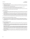
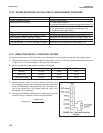
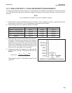
A. Disconnect the anode and cathode leads from terminals 1 and 2 on TB3 and connect a decade box and bat-
tery as shown in Figure 16-2. It is not necessary to disconnect the RTD leads.
B. Set the decade box to the resistance shown in the table.
C. Note the sensor current. It should be close to the value
in the table. The actual value depends of the voltage of
the battery. To view the sensor current from the main
display, press any key to enter the main menu. Move
the cursor to "Diagnostics" and press Enter (F4). The
sensor current is the second line in the display. Note
the units: μA is microamps, nA is nanoamps.
D. Change the decade box resistance and verify that the
correct current is shown. Calculate current from the
equation:
current (μA) =
The voltage of a fresh 1.5 volt battery is about 1.6 volt
(1600 mV).
Sensor Polarizing Voltage Resistance Expected current
499ACL-01 (free chlorine) 200 mV 28 MΩ 500 nA
499ACL-02 (total chlorine) 250 mV 675 kΩ 2000 nA
499ACL-03 (monochloramine) 400 mV 3 MΩ 400 nA
499AOZ 250 mV 2.7 MΩ 500 nA
V
battery
- V
polarizing
(mV)
resistance (kΩ)
FIGURE 16-2. Simulate Chlorine and Ozone
103