


MODEL 54eA SECTION 16.0
TROUBLESHOOTING
16.4.1 Zero current is too high
A. Is the sensor properly wired to the analyzer? See Section 3.3.
B. Is the membrane completely covered with zero solution and are air bubbles not trapped against the mem-
brane? Swirl and tap the sensor to release air bubbles.
C. Is the zero solution fresh and properly made? Zero the sensor in a solution of 5% sodium sulfite in water.
Prepare the solution immediately before use. It has a shelf life of only a few days.
D. If the sensor is being zeroed with nitrogen gas, verify that the nitrogen is oxygen-free and the flow is adequate
to prevent back-diffusion of air into the chamber.
E. The major contributor to the zero current is dissolved oxygen in the electrolyte solution inside the sensor. A
long zeroing period usually means that an air bubble is trapped in the electrolyte. To ensure the 499ADO or
499A TrDO sensor contains no air bubbles, carefully follow the procedure in the sensor manual for filling the
sensor. If the electrolyte solution has just been replaced, allow several hours for the zero current to stabilize.
On rare occasions, the sensor may require as long as overnight to zero.
F. Check the membrane for damage and replace the membrane if necessary
.
16.4.2 Zero reading Is unstable.
A. Is the sensor properly wired to the analyzer? See Section 3.3. Verify that all wiring connections are tight.
B. Readings are often erratic when a new or rebuilt sensor is first placed in service. Readings usually stabilize
after an hour.
C. Is the space between the membrane and cathode filled with electrolyte solution and is the flow path between
the electrolyte reservoir and the membrane clear? Often the flow of electrolyte can be started by simply hold-
ing the sensor with the membrane end pointing down and sharply shaking the sensor a few times as though
shaking down a clinical thermometer. If shaking does not work, perform the checks below. Refer to the sensor
instruction manuals for additional information.
For 499ADO and 499A TrDO sensors, verify that the holes at the base of the cathode stem are open (use a
straightened paperclip to clear the holes). Also verify that air bubbles are not blocking the holes. Fill the reservoir
and establish electrolyte flow to the cathode. Refer to the sensor instruction manual for the detailed procedure.
For Gx438 and Hx438 sensors, the best way to ensure that there is an adequate supply of electrolyte solution
is to simply add fresh electrolyte solution to the sensor. Refer to the sensor instruction manual for details.
16.4.3 Sensor can be calibrated, but current in air is too high or too low
A. Is the sensor properly wired to the analyzer? See Section 3.3. Verify that all connections are tight.
B. Is the membrane dry? The membrane must be dry during air calibration. A droplet of water on the membrane
during air calibration will lower the sensor current and cause an inaccurate calibration.
C. If the sensor current in air is very low and the sensor is new, either the electrolyte flow has stopped or the mem-
brane is torn or loose. For instructions on how to restart electrolyte flow see Section 16.4.2 or refer to the sen-
sor instruction manual. To replace a torn membrane, refer to the sensor instruction manual.
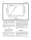
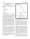
D. Is the temperature low? Sensor current is a strong function of temperature. The sensor current decreases
about 3% for every °C drop in temperature.
E. Is the membrane fouled or coated? A dirty membrane inhibits diffusion of oxygen through the membrane,
reducing the sensor current. Clean the membrane by rinsing it with a stream of water from a wash bottle or by
gently wiping the membrane with a soft tissue. If cleaning the membrane does not improve the sensor
response, replace the membrane and electrolyte solution. If necessary, polish the cathode. See the sensor
instruction sheet for more information.
16.4.4 Possible error warning during in-process calibration
This error warning appears if the current process reading and the reading it is being changed to, ie, the reading
from the standard instrument, are appreciably different.
A. Is the standard instrument properly zeroed and calibrated?
B. Are the standard and process sensor measuring the same sample? Place the sensors as close together as
possible.
C. Is the process sensor working properly? Check the response of the process sensor in air and in sodium sul-
fite solution.
89