


16
SECTION 5 – REPLACEABLE PARTS
5.1 Ordering Information
The following information must be supplied when ordering a replacement part from your service agent in
order to ensure that the correct part is supplied:
A. Model or Spec. number of charger (Located on charger data plate)
B. Serial number of charger (Located on charger data plate)
C. Schematic reference symbol or part
D. Description of part
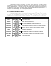
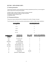
5.2 Recommended Spares
The quantity of spares stocked should be increased as the number of chargers increases.
The following chart is the minimum quantity recommended per model for multiple charger installations:
# OF CHARGERS
# OF SPARE PARTS KITS
1-3 1
4-10 2
11-25 3
26-50 4
51-100
5
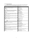
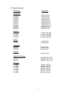
SCHEMATIC REF
SYMBOL
DESCRIPTION
QUAN. USED QUANTITY RECOMMENDED
ACF AC FUSE, 1 PH. 2 4
ACF AC FUSE, 3 PH. 3 6
DCF DC FUSE 1 2
CONTROL CONTROL BOARD 1 1
AK A.C. CONTACTOR 1 1
SD1,SD2 SILICON DIODE, 1 PH. 2 2
SD1-SD6 SILICON DIODE, 3 PH. 6 3
TP TRANSFORMER, 1 PH. 1 0
TP TRANSFORMER, 3 PH 3 0
C CAPACITOR VARIES 1
CT CONTROL TRANSFORMER 1 1