


6
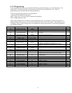
TABLE 1-1
Line Amperes Disconnect Switch Fuse Size Amps
000.0 - 02.5 30A 05
003.0 - 04.5 30A 07
005.0 - 07.5 30A 10
008.0 - 11.0 30A 15
011.5 - 15.5 30A 20
016.0 - 18.0 30A 25
018.5 - 22.0 30A 30
022.5 - 27.0 60A 35
027.5 - 32.0 60A 40
032.5 - 40.0 60A 50
040.5 - 48.0 60A 60
048.5 - 64.0 80A 80
065.0 - 80.0 100A 100
081.0 - 95.0 125A 125
096.0 - 125.0 150A 150
1.4. AC Service Requirements
Follow local code requirements if they are different than the instructions in this manual. After checking
the transformer connections as described in Paragraph 1.3, refer to Table 1-1, to determine the correct
ratings for the AC cable, AC fuses, and AC service disconnect switch for the line amperes as listed on
the nameplate of the charger for the available AC voltage
For voltages up to 240, use a 240 volt disconnect switch.
For voltages greater than 240 to 600, use a 600 volt disconnect switch.
• Two conductors and ground wire required for single phase.
• Three conductors and ground wire required for three-phase
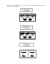
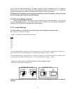
1.5. Connecting AC Service to the Charger
1.5.1 Single-Phase Models
Connect the AC service to the L1 and L2 terminals located at the end of the AC fuse block.
Note: If the charger has been ordered with an AC input door-mounted disconnect switch, the AC input
wires will be connected to the L1 and L3 terminals at the top of the switch body.
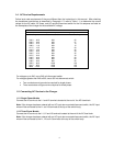
1.5.2 Three-Phase Models
Connect the AC service to the L1, L2 and L3 terminals located at the end of the AC fuse block.
Note: If the charger has been ordered with an AC input door-mounted disconnect switch, the AC input
wires will be connected to the L1, L2 and L3 terminals at the top of the switch body.