


7
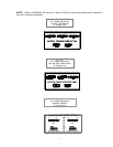
1.6 Grounding the Charger
The charger must be grounded to the AC system ground for personnel safety.
The green ground wire in the AC input wiring must be connected to the charger ground stud
(Identified by a green dot and ground symbol).
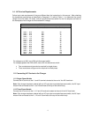
1.7 Battery Connector and Charging Cable
Verify that the connectors on both the battery and the charger are attached so that the positive
output terminal of the charger is connected to the positive battery terminal.
CAUTION: If the polarity is reversed, the DC fuse will blow.
If in doubt, check the polarity with a DC voltmeter.
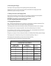
1.8 Charging Rate Adjustment
Note: Charging rate adjustments may be necessary to compensate for locations of extreme AC line
variation or may be used to tailor the charger output for aging batteries.
The charging rate has been set at the factory; therefore, field adjustment should not be necessary.
If there appears to be a charging rate problem, refer to the troubleshooting chart, Section 4.
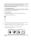
If it is necessary to either increase or decrease the charging rate, a rate adjustment terminal block is
provided on the top rear of the transformer mounting bracket.
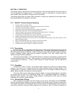
Change only one step at a time and observe the effect on the battery before making a second change.
The charging rate is increased by moving to the next higher tap setting in Table 1-2.
The charging rate is decreased by moving to the next lower tap setting.
No adjustments should be made without consulting the factory.
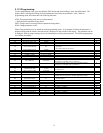
TABLE 1-2
CHARGING RATE ADJUSTMENTS
CONNECT RED
JUMPER WIRE TO
CONNECT
BLACK WIRE TO
OUTPUT
9 12 HIGHEST
9 11
9 10
9 8 NORMAL
12 11
12 10
12 9 LOWEST