


4. After the cut is complete, unplug the saw for safety, but
leave it on the guide rail.
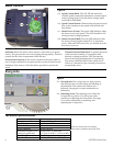
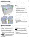
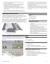
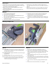
5. Lower the sawblade to its maximum depth and examine
the gap between the blade and the workpiece using a
regular piece of paper as a thickness gauge.
► The front of the blade should be tight to the workpiece.
You should not be able to slip the paper between the blade
and workpiece.
► The rear of the blade should be 0.15mm away from the
workpiece. The paper should fit loosely between the blade
and workpiece, but two sheets of paper should not fit.
6. If an adjustment is necessary, loosen the rear bevel
locking knob and move the back of the saw until the
0.15mm gap is achieved.
7. Retighten the bevel locking knobs before removing the
saw from the guide rail, and then retighten the other
screws. (Set the bevel pointer to zero before tightening
the screw.)
Replacing the Splinter Guard
The splinter guard prevents splintering and chipping of the
workpiece by holding the top edge of the workpiece down as the
teeth of the sawblade move upward against it. The splinter guard
needs to be replaced if it becomes damaged or worn.
Because the splinter guard is trimmed by the sawblade, it is important
that the sawblade is properly adjusted before replacing the splinter
guard. Verify and/or perform the "Adjusting the Blade Position"
procedure described on page 10 before replacing the splinter guard.
Instruction Manual 11
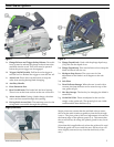
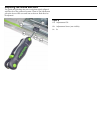
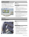
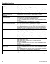
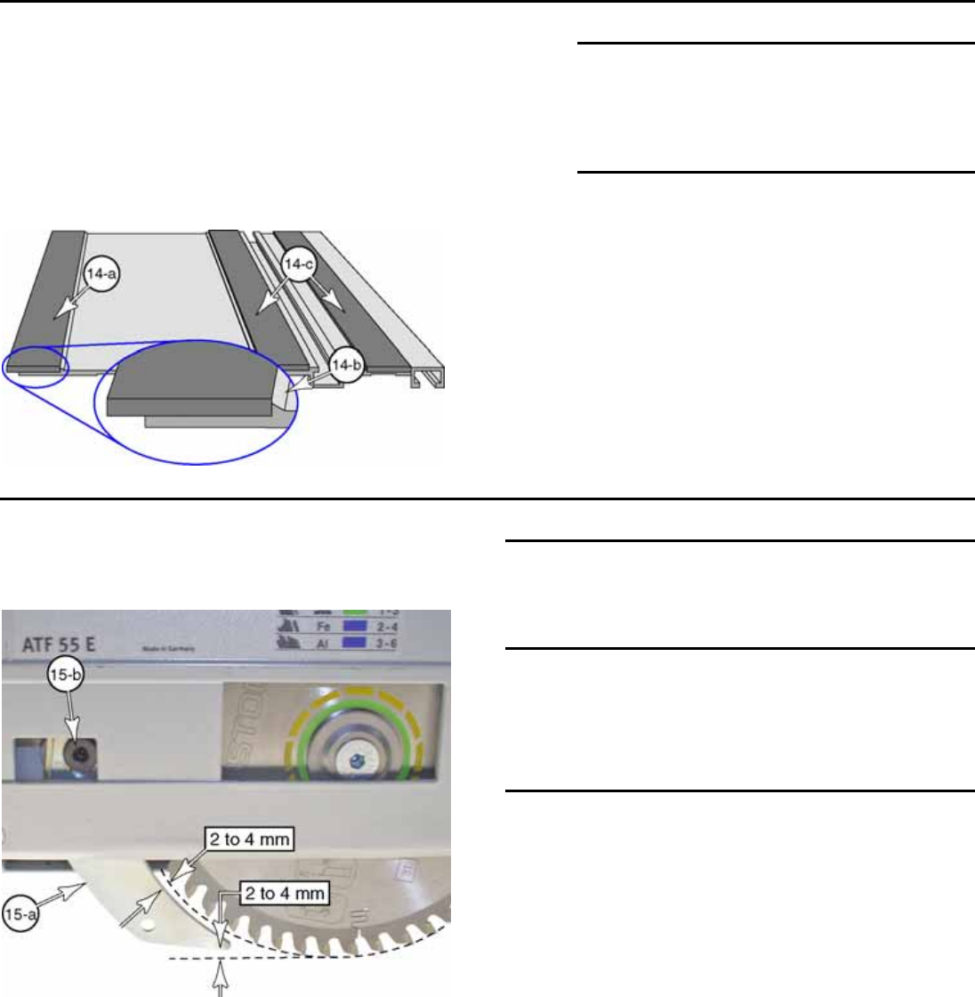
Figure 14
14-a Splinter Guard
14-b Alignment Rib
14-c Friction Strips
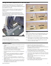
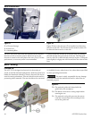
Replacement Procedure
1. Peel the original splinter guard away from the
guide rail.
2. As needed, clean residual adhesive and debris
from the guide rail.
3. Peel off the plastic backing from the new
splinter guard to expose the adhesive.
4. Without stretching the rubber, carefully place
the new splinter guard on the underside of the
guide rail tight to the alignment rib (14-b).
5. Make sure the splinter guard is firmly pressed
down to the guide rail.
6. Trim the splinter guard as described on page 8.
Removing/Replacing/Adjusting the Riving Knife
The riving knife must be removed before a plunge cut can be
made. After it is reinstalled, it must be adjusted for proper
clearance.
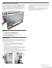
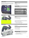
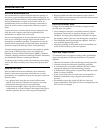
Figure 15
15-a Riving Knife
15-b Adjustment Screw
Removal Procedure
1. Unplug the saw.
2. Loosen the adjustment screw (15-b).
3. Remove the riving knife and retighten the adjustment
screw.
Replacement/Adjustment Procedure
1. Unplug the saw.
2. Loosen the adjustment screw (15-b).
3. Insert the riving knife under the adjustment screw.
4. Move the riving knife to achieve the clearance from the
blade as shown in figure 15.
5. Tighten the adjustment screw.