


Changing the Motor Brushes
This procedure should be completed only by an authorized
Festool service representative. Opening the motor cover
WILL void your warrantee. This procedure is presented as
informational only.
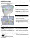
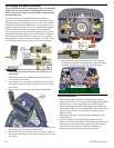
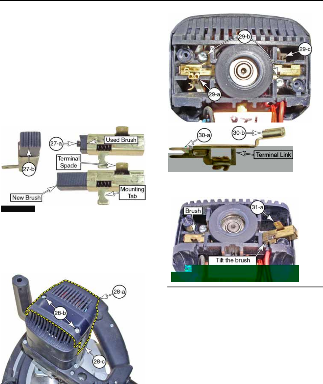
The motor brushes are graphite bars that provide an
electrical connection between the motor controller and the
rotating armature. The brushes wear over time and need to
be replaced. When the brushes have worn past their useful
length, spring loaded pins (27-a) are exposed that separate
the brush from the armature contacts. This disables the
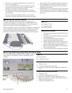
motor to prevent damage. When the brushes are worn, the
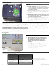
green power indicator (figure 4-c) will illuminate when the
saw is powered, but the motor will not run. For a shorter
break-in period without excessive arcing, new brushes have
ribs (27-b) that quickly form to the curve of the armature.
18 ATF 55E Circular Saw
!WARNING: Make sure the power cord is unplugged before
beginning this procedure. Failure to do so may result in
electrocution.
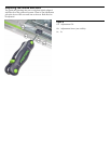
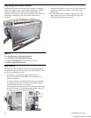
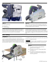
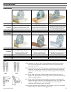
1. Remove the two screws (28-b) that secure the access
cover (28-a) to the motor.
2. As necessary, cut or remove any labels that may cover
the seams between the motor and the access cover (28-c,
both sides).
3. Remove the cover to expose the motor and brushes.
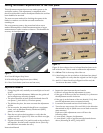
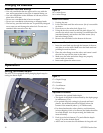
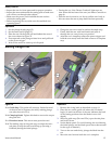
4. Lift the terminal links (29-a and figure 30) straight up off
the brushes and out of their sockets (29-c).
5. Remove the two screws (29-b) that secure the brushes to
the motor housing. Be careful not to drop the screws into
the motor.
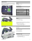
6. The brushes are spring-loaded in their brass sleeves.
During both removal and replacement, tilt the brushes
as shown in figure 31 to clear the motor housing.
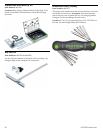
Replacement Notes
► When replacing the brushes, tilt them into position as
shown in figure 31, and compress the spring loaded brush
assembly as you insert them into their mounting slots.
► When replacing the terminal links (figure 30), make sure
the forked spades (30-a) are inserted into the sockets (29-c),
and the lugs (30-b) are connected to the spades on the
brushes (31-a).
► Finish the procedure by reversing the remainder of the
removal steps.
► Note that during the break-in period while the new
brushes conform to the shape of the armature contacts, the
brushes my exhibit more arcing (sparking) than normal.
The ribs (27-b) on the new brushes are intended to
minimize the arcing during the break-in period.