


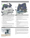
Setting the Blade Perpendicular to the Sole plate
This adjustment ensures that cuts are made square to the
workpiece surface. This adjustment is completed at the
factory and shouldn’t need to be adjusted unless the tool has
been modified or serviced.
The most accurate method for checking the square of the
blade is to make a cut with the saw and examine the
resulting cut.
For even greater accuracy, the procedure below uses a
method that amplifies a small measurement into a larger
measurement to make it easier to observe. This doubles the
accuracy of the adjustment.
Instruction Manual 9
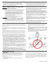
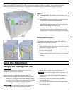
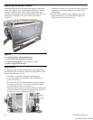
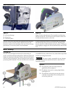
Figure 9
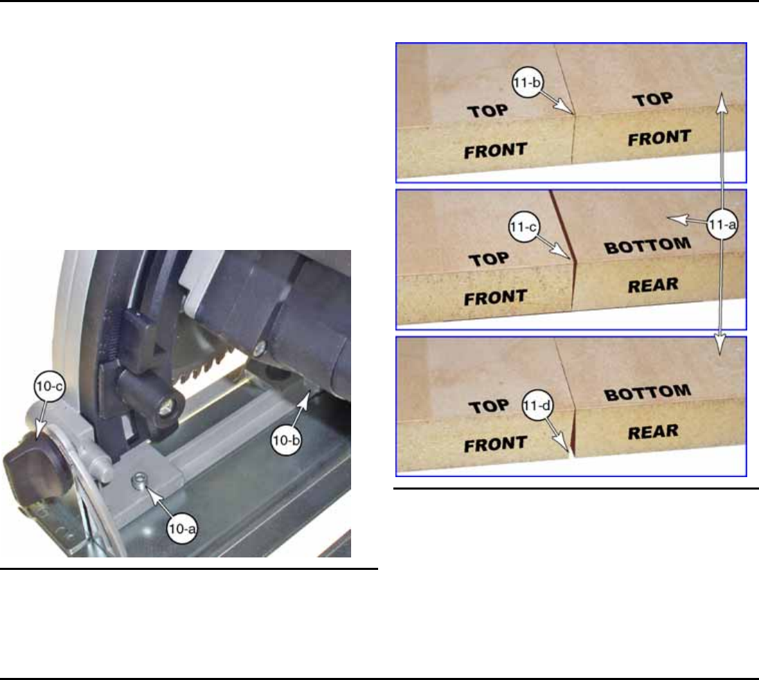
10-a Front 90-degree Stop Screw
10-b Rear 90-degree Stop Screw (not visible)
10-c Bevel Lock knobs (one front and one rear)
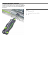
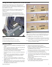
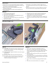
Figure 11
Figure 11 shows three views of a board that has been cut in
half with the saw. This is used to calibrate the adjustment.
11-a Offcut. This is the scrap-side of the cut.
11-b After being cut, the two halves of the board are placed
back together to verify that the original cut-line is tight.
11-c and 11-d After the offcut is flipped end-for-end, the
bevel-error becomes visible.
Adjustment Procedure
1. Using the guide rail, carefully cut a small piece of wood
in half.
► This is a precision adjustment. Make sure the guide rail
and workpiece are securely clamped.
► The piece should be at least 20 mm thick and about 30
cm square (¾ inch thick by 12 inches square).
► The thicker the piece, the more accurate the adjustment
will be.
► For best results, the material should have a consistent
center, such as Medium Density Fiberboard (MDF),
plastic, or solid lumber.
2. Place the two pieces back together to verify that the
original cut-line is tight (11-b). If the cut-line is not tight,
make a new cut.
3. Flip the offcut board (11-a) end-for-end so the cut-line is
still together, but the board is upside down. (Don't flip
the board that was under the saw.)
4. Inspect the joint between the two boards:
► If there is no gap then the adjustment is correct.
► If the gap is at the top of the two boards (11-c), then turn
the adjustment screws clockwise.
► If the gap is at the bottom of the two boards (11-d), then
turn the adjustment screws counterclockwise.
5. Loosen the front and rear bevel lock knobs (10-c).
6. Turn the two stop screws (10-a and 10-b) in the direction
determined in step 4. (Make sure to turn both screws the
same amount.)
Each turn of the adjustment screw will have the
following effect:
► 1 turn equals 1 degree of adjustment.
► 1 turn equals ½ mm of gap between the boards shown
above (assuming 20 mm (¾ inch) th92 3