


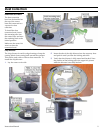
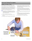
Plunge Routing
Plunge routing is any operation where the router is
lowered down into the cutting area after the router has
been started. Most often this involves router bits that do
not have a guide bearing, but can also be used for interior
cutting (such as the circular cut shown on page 12).
Instruction Manual 13
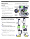
!WARNING: Take care while plunge routing to maintain
control of the router at all times. For many plunge
operations, one side of the router bit will be climb-
cutting and the other side will be push-cutting. This
can lead to a loss of control and/or poor cut quality.
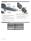
1. Verify that the router bit is properly secured and the
router is ready for operation.
2. Secure the workpiece to a stable surface.
3. Set the router speed according to the speed settings
table below.
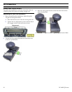
4. With the router turned off, place the router on the
workpiece.
5. Firmly grasp both handles of the router and pull up on the
power switch.
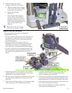
6. Lower the router to the desired depth, tighten the plunge
lock knob, and advance the router through the cut.
!WARNING: Failure to tighten the plunge lock knob may
result in a loss of control and injury.
► For router bits with guide bearings, advance the router
through the cut according to the feed direction rules
discussed on page 12.
► When using router bits without a guide bearing, or with an
external guide rail, follow the tips in "plough cuts" below
to keep the router tracking properly.
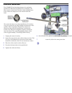
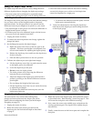
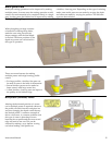
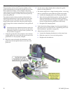
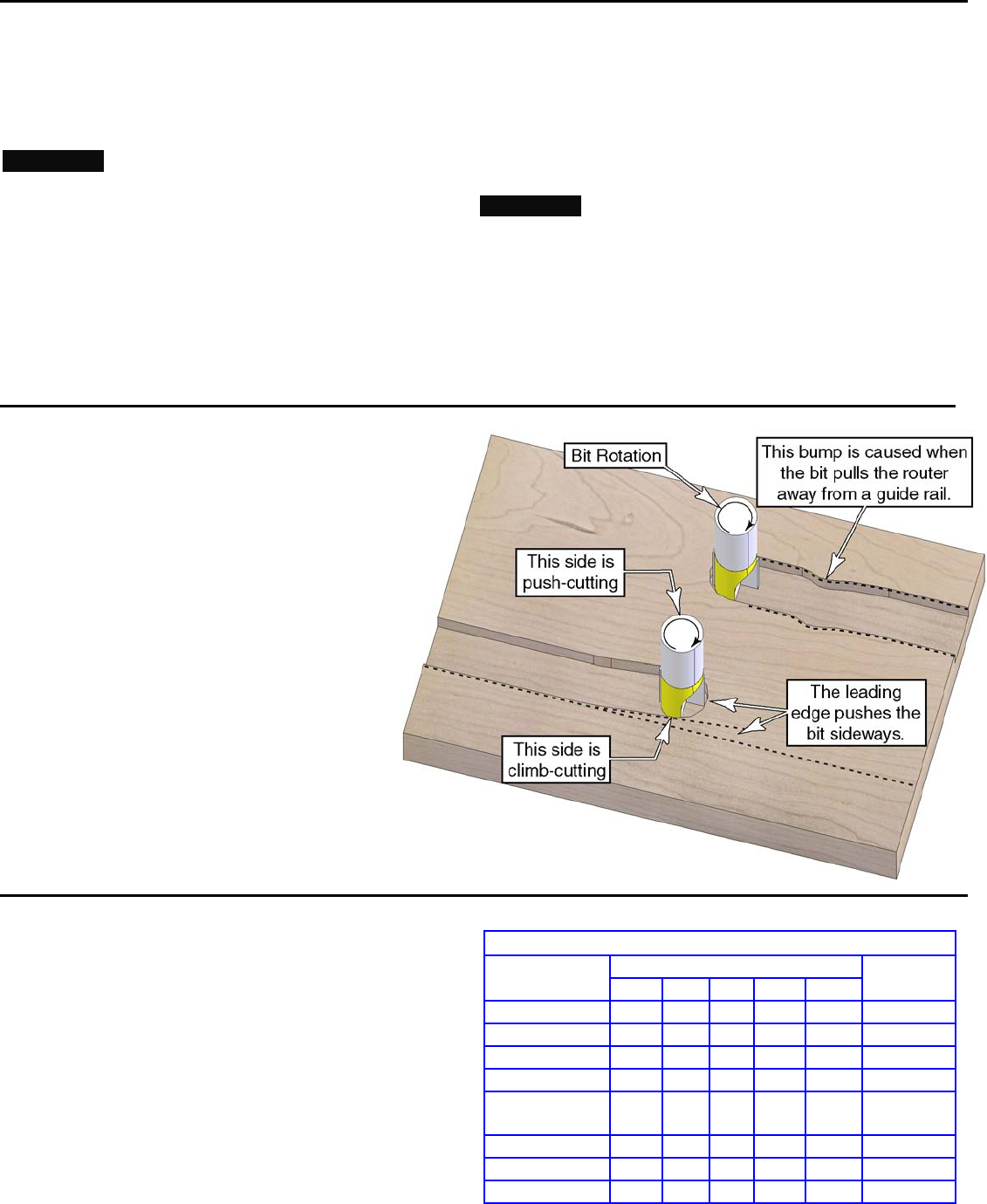
Plough Cuts
When making plough cuts, as shown to the right,
three sides of the router bit are engaging the
workpiece. This can lead to undesired changes in
the path of the router.
► One side of the router bit is climb-cutting, and
this tends to propel the router forward.
► One side of the router bit is push-cutting, and
this tends to slow the feed rate.
► The leading edge of the router bit pushes the
router sideways, opposite the rotation of the bit.
The opposing climb-cutting and push-cutting sides
will cause the router to advance with a jerking
motion.
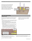
To avoid drift from the leading edge of the router
bit, position a guide rail on the push-cutting side of
the router (toward the middle in the image to the
right).
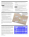
Router Speed and Feed Rate
The optimal router speed for an operation is determined
by the diameter of the router bit and the type of material
being machined. The important factor is the speed that the
router bit tips move past the workpiece. The tip speed is
proportional to the diameter of the router bit.
If the tip speed is too high, friction causes excessive heat
and the workpiece can be scorched. Too low of a tip speed
and the bit will tear the material instead of cutting (for
aluminum, the bit will grab the workpiece).
The feed rate of the router past the workpiece is a function
of the router speed, material type, and amount of material
being removed. Too fast of a feed rate can cause chatter
and tearout. Too slow of a feed rate can burn or scorch the
workpiece.
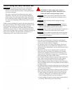
Router Speed Settings
Bit Diameter (inches)
Material
≤½ ¾ 1 1¼ ≥1½
Feed
Rate
Pine
5-6 5-6 4-6 3-5 3-5 Fast
Oak
5-6 4-6 4-5 3-5 2-4 Moderate
Cherry
3-5 3-5 3-4 2-4 2-3 Moderate
Maple
3-5 3-5 3-4 2-4 2-3 Slow
Particleboard
and MDF
5-6 5-6 4-6 3-5 3-5 Fast
Soft Plastics
3-5 3-5 3-4 2-4 1-3 Slow
Hard Plastics
2-4 1-4 1-3 1-2 1-2 Slow
Aluminum
3-4 3-4 2-3 2-3 1-3 Slow