


Instruction Manual 19
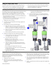
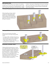
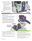
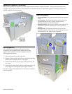
6. Install and adjust the leveling
outrigger to the back of the router.
a. Adjust the height of the outrigger
so the router is level when sitting
on the edge of the guide rail.
b. Tighten the clamping
thumbscrew.
► The router bit radius gauge is
used to indicate the location of
the edge of the router bit. This is
helpful for making stopped cuts.
Note that this gauge indicates the
radius of the bit and not the
diameter.
Make sure to raise the outrigger
out of the way when not in use.
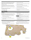
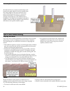
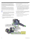
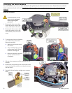
Us g the Guide Rail Attachment in
1. Clamp the guide rail to the workpiece. Note that the
cutting action of the router bit may tend to move the
guide rail if it is not properly clamped.
2. Place the router and guide rail attachment on the guide
rail with the outer guide block on the first rib of the
guide rail.
3. Verify that the leveling outrigger is at the proper height
so the router base is level (see procedure above).
4. Loosen the clamping thumbscrew on the router, and
slide the router in or out to its approximate final
position. Retighten the thumbscrew.
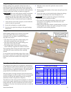
5. With the inner guide block clamping knob tight and the
outer guide block clamping knob loose, adjust the micro-
adjust thumbwheel to set the final position of the router:
► Each number on the wheel represents 0.1mm, and a full
turn of the wheel represents 1.0 mm.
► After the micro-adjustment is complete, tighten the
outer guide block clamping knob.
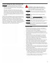
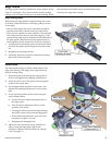
The Festool
g
uide rail is used as a conven
htedge for routing.
ient
straig
► The zero-clearance strip does not serve a purpose for
this operation, so take care not to cut into the strip.
(Keep the router bit at least ¼-inch away from the
zero
► ing as a
straightedge, the router can be placed on the guide
rail in any one of several ways, depending on the
need. (Also refer to the procedure on the next page.)
► In o t feature, the
gui talled on the guide
rail with the inner guide block free to move, as
sho
-clearance strip.)
Because the guide rail is simply serv
rder to utilize the micro-adjustmen
de rail attachment must be ins
wn.