


Operation
14 3A2308C
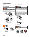
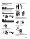
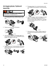
Install Tip/Guard Assembly
(if not installed)
NOTE: Only use Graco Tip/Guard assemblies.
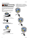
1. Engage trigger lock and put prime/pressure relief
valve UP to relieve pressure.
2. Screw Tip/Guard Assembly onto sprayer. Tighten
retaining nut until completely engaged with sprayer.
Do not overtighten nut.
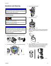
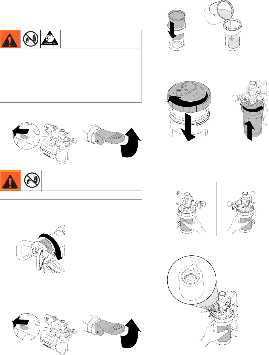
Filling and Installing Cup
1. Engage trigger lock and put prime/pressure relief
valve UP to relieve pressure.
2. Install liner into material cup and fill with material.
3. Thread lid onto material cup and connect cup to
sprayer. NOTE: Do not squeeze sides of cup while
threading lid onto cup.
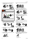
NOTE: Check valve can be oriented in three loca-
tions when attached to cup. If squeezing liner with
left hand, position check valve on left side. If
squeezing liner with right hand, position check valve
on right side.
4. Squeeze liner to purge air through check valve until
material is present at check valve.
NOTE: To purge the maximum amount of air out of
the liner, slightly tilt the sprayer so the check valve is
the highest point.
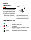
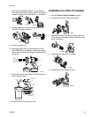
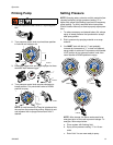
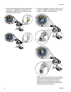
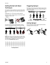
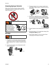
This equipment stays pressurized until pressure is
manually relieved. To help prevent serious injury
from pressurized fluid, such as skin injection,
splashing fluid and moving parts, follow the
Pressure Relief Procedure when you stop spraying
and before cleaning, checking, or servicing the
equipment.
Do NOT place hands in front of tip.
ti19347a
ti19350a
ti19369a
ti19347a
ti19350a
ti19348a
ti19354a
ti19384a
ti19355a
ti19367a