


Repair
3A2308C 35
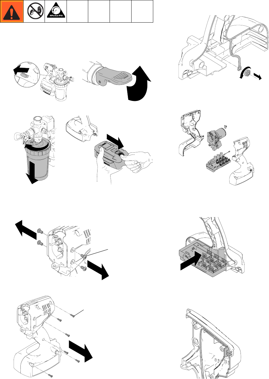
Motor/Control Board Replacement Kit
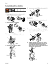
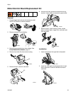
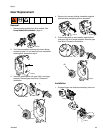
Removal
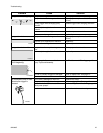
1. Engage trigger lock and put prime/pressure relief
valve in UP position to relieve pressure.
2. Remove material cup and battery.
3. Remove pump module from drive module. See
Pump Module/Drive Module, page 31.
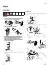
4. Remove four bolts (42) from motor housing.
5. Remove screws (43) from clamshell.
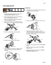
6. Unscrew nut from ground stud and remove ring
terminal. Leave other nut secured to ground stud.
7. Remove motor, motor housing, switch, control
board, indicator lights, trigger lock, and static wick
from clamshell.
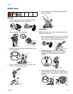
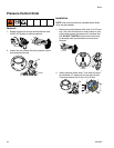
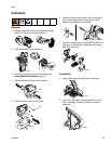
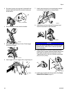
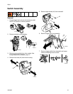
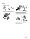
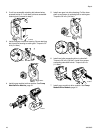
Installation
1. Insert control board into right half of clamshell.
2. Install two LED lights into designated slot in right
half of clamshell. Push wire bundle into slots in
clamshell.
ti19350a
ti19347a
ti19360a
ti19617a
ti19636a
42
ti19637a
43
ti19640a
ti19639a
ti19627a
ti19628a