


Repair
36 3A2308C
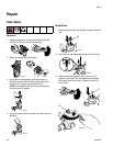
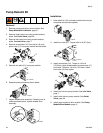
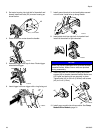
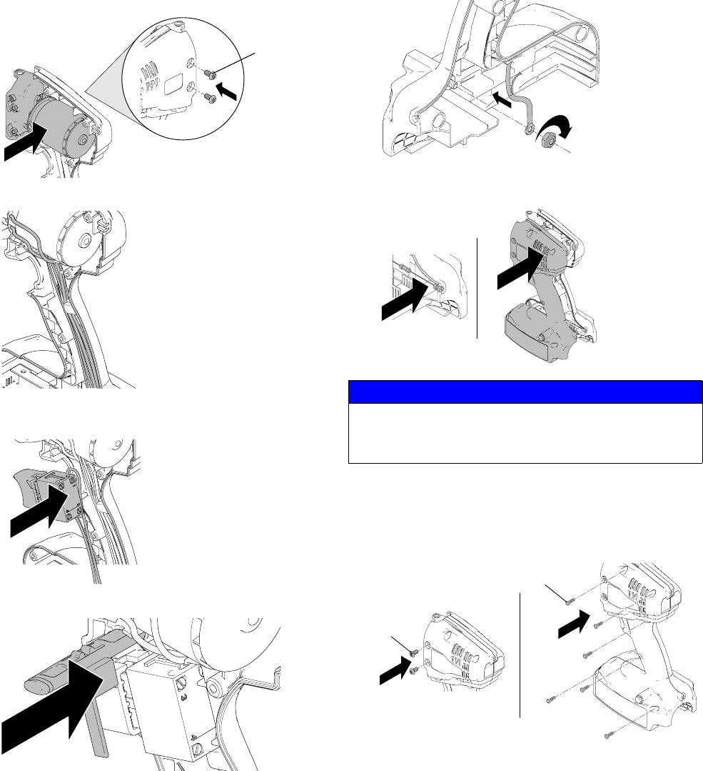
3. Set motor housing into right half of clamshell and
loosely install two bolts (42) to motor housing as
shown below.
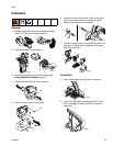
4. Route wires from motor down the handle.
5. Assemble trigger over top of wires. Route trigger
wires behind trigger.
6. Insert trigger lock over trigger with o-ring facing out.
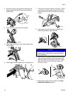
7. Install ground terminal to stud and tighten second
nut onto stud. Install wire up along handle.
8. Insert static wick into right half of clamshell and
install left clamshell to right clamshell.
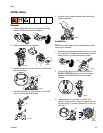
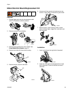
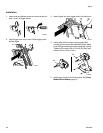
9. Install two bolts (42) to motor housing and install
screws (43) to connect clamshell halves. Make sure
LED lights and static wick are securely in place.
Tighten bolts (42) to 50 in-lb (5.6 N•m) and screws
(43) to 9 in-lb (1 N•m).
10. Install pump module into drive module. See Pump
Module/Drive Module, page 31.
ti19629a
42
ti19630a
ti19631a
ti19632a
NOTICE
Wires can become damaged when pinched between
clamshell halves. Make sure no wires are pinched
during reassembly.
ti19641a
ti19634a
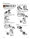
ti19635
a
42
43