


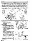
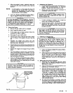
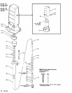
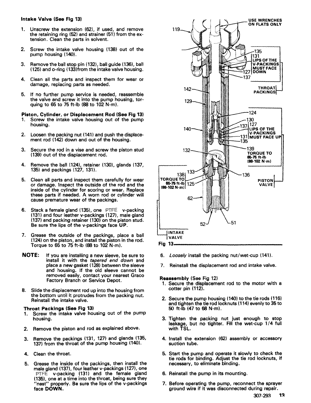
Intake
Valve
(See Fig
13)
1.
Unscrew the extension (62),
if
used, and remove
the retaining ring
(52) and strainer
(51)
from the ex-
tension. Clean the parts
in
solvent.
2.
Screw the intake valve housing
(138)
out
of
the
pump housing (140).
3. Remove the
ball stop pin (132), ball guide (136), ball
(125)
and o-ring (133)from the intake valve housing.
4.
Clean
all the parts and inspect them
for
wear or
damage, replacing parts
as
needed.
5.
If no further pump service is needed, reassemble
the
valve and screw
it
into the pump housing, tor-
quing
to
65
to
75
ft-Ib (88
to
102
N·m).
Piston,
Cylinder,
or
Displacement
Rod (See Fig
13)
1.
Screw the intake valve housing
out
of
the pump
housing.
2.
Loosen the packing nut
(141)
and push the displace-
ment rod
(142)
down and out
of
the housing.
3. Secure the rod
in
a vise and screw the piston stud
(139)
out
of
the displacement rod.
4.
Remove the ball (124), retainer (130), glands (137,
135)
and packings
(127,
131).
5.
Clean
all parts and inspect them carefully
for
wear
or damage. Inspect the outside
of
the rod and the
inside
of
the cvlinder
for
scoring or wear. Replace
these parts
if
needed. A worn rod or cylinder will
cause premature wear
of
the packings.
6.
Stack a female gland (135), one PTFE v-packing
(131)
and four leather v-packings (127), male gland
(137)
and packing retainer
(130)
on
the piston stud.
Be
sure the lips
of
the v-packings face UP.
7.
Grease
the outside
of
the packings, place a ball
(124)
on the piston, and install the piston in the rod.
Torque
to
65
to
75 ft-Ib (88
to
102
N·m).
NOTE:
If
you
are
installing a new sleeve, be sure
to
install it with the tapered end down and
place a new gasket
(128)
between the sleeve
and housing.
If
the old sleeve cannot be
removed easily, contact your nearest Graco
Factory Branch or
Service Depot.
8. Slide the displacement rod up into the housing from
the bottom until
it
protrudes from the packing nut.
Reinstall the intake valve.
Throat
Packings
(See Fig
13)
1.
Screw the intake valve housing out
of
the pump
housing.
2. Remove the piston and rod
as
explained above.
3. Remove the pac kings
(131,
127)
and glands (135,
137)
from the throat
of
the pump housing (140),
4.
Clean
the throat.
5. Grease the inside
of
the packings, then install the
male gland (137), four leather v-packings (127), one
PTFE v-packing
(131)
and the female gland
(135), one at a time into the throat, being sure they
"nest"
properly.
Be
sure the lips
of
the v-packings
face
DOWN.
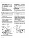
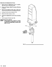
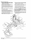
INTAKE
VALVE
USE WRENCHES
ON FLATS ONLY
135
31
LIPS
OFTHE
.~~-----=:::...<-...,
V-PACKINGS
MUST
FACE
DOWN
137
THROAT
PACKINGS
124
30
127
LIPS
OF
THE
V-PACKINGS
a---'~'
MUST
FACE UP
35
139
TORQUE TO
66-76 ft-Ib
(88-102 N·m)
PISTON
VALVE
Fig
13-------
_______
_
6.
Loosely install the packing nut/wet-cup (141).
7.
Reinstall the displacement rod and intake valve.
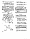
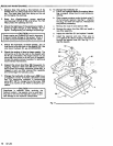
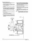
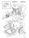
Reassembly
(See
Fig
12)
1.
Secure the displacement rod to the motor
with
a
cotter pin (112).
2. Secure the pump housing
(140)
to the tie rods
(116)
and tighten the tie rod locknuts
(114)
evenly
to
35
to
50 ft-Ib
(47
to
68 N·m).
3. Tighten the packing nut just enough
to
stop
leakage,
but
no
tighter.
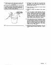
Fill
the wet-cup
1/4
full
with
TSL.
4.
Install the extension
(62)
assembly or accessory
suction tube.
5.
Start the pump and operate it slowly to check the
tie rods
for
binding. Adjust the tie rod locknuts,
if
necessary,
to
eliminate binding.
6.
Reinstall the pump in its mounting.
7. Before operating the pump, reconnect the sprayer
ground wire
if
it
was disconnected during repair.
307-293
1~