


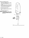
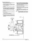
Drive
Unit
(See Figs 14 and
15)
1.
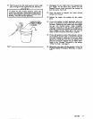
Disconnect the hydraulic inlet hose
(92)
from the
paint pump's
90°
swivel union (45),
2. Loosen the coupling
nut
of
the elbow (41) and
disconnect the hydraulic oil drain hose
(2) from the
oil cooler inlet elbow
(41).
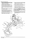
3.
Disconnect the bypass hose (85) from the bypass
valve
(84).
4.
Remove the oiler cooler
(69),
the fan guard (76), the
cooler retaining screw
(40) and clamp
(68),
and the
drain hose
(2).
Loosen the cooler drain connector
nut
(42).
Pull the cooler up, out
of
the housing.
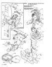
5. Remove the locknuts
(27)
from the
four
engine
mounts (31).
6.
Remove the four locknuts
(27)
from the filter seal
plate
(160) screws.
7. Lift up the entire drive assembly (engine, fan, and
hydraulic pump) and
tilt
it
forward.
8. Remove the
four
screws
(12)
holding the cooler
housing
(60)
to
the adapter plate (64) and take the
hydraulic pump
(70) and cooler housing
off
of
the
engine (32).
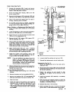
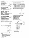
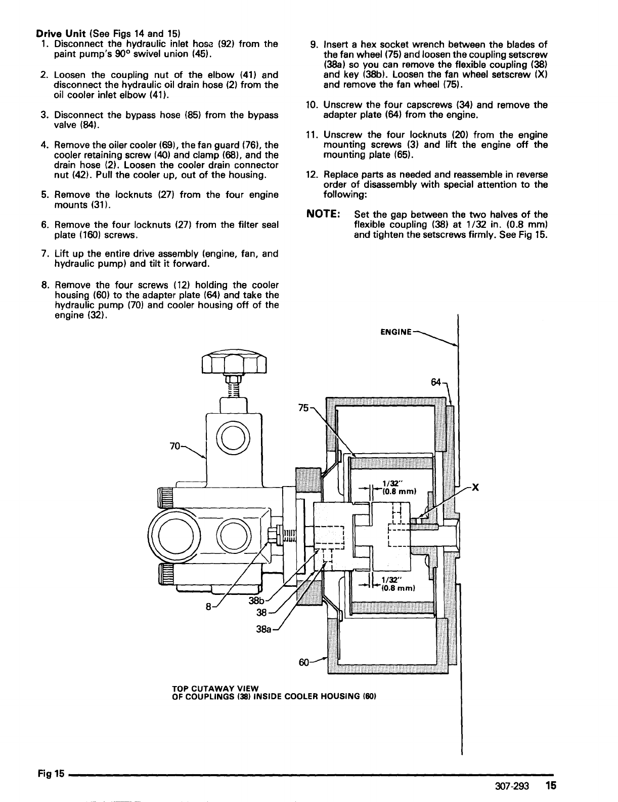
TOP
CUTAWAY
VIEW
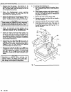
9.
Insert a hex socket wrench between the blades
of
the fan wheel (75) and loosen the coupling setscrew
(38a) so you can remove the flexible coupling
(38)
and key (38b). Loosen the fan wheel setscrew (X)
and remove the fan wheel (75).
10.
Unscrew the
four
capscrews
(34)
and remove the
adapter plate
(64) from the engine.
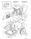
11. Unscrew the
four
locknuts (20) from the engine
mounting screws
(3) and
lift
the engine
off
the
mounting plate
(65).
12.
Replace parts
as
needed and reassemble in reverse
order
of
disassembly with special attention
to
the
following:
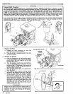
NOTE: Set the gap between the
two
halves
of
the
flexible
coupling
(38)
at 1/32 in. (0.8 mm)
and tighten the setscrews firmly. See Fig
15.
X
OF
COUPLINGS
(38)
INSIDE COOLER HOUSING
(60)
Fig15
________________________________________________________________________
__
307-293
15