


TERMS
WARNING:
Alerts user to avoid or correct conditions
that
could cause bodily injury.
CAUTION: Alerts user
to
avoid or correct conditions
that
could
cause
damage to or destruction
of
equipment.
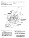
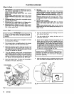
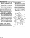
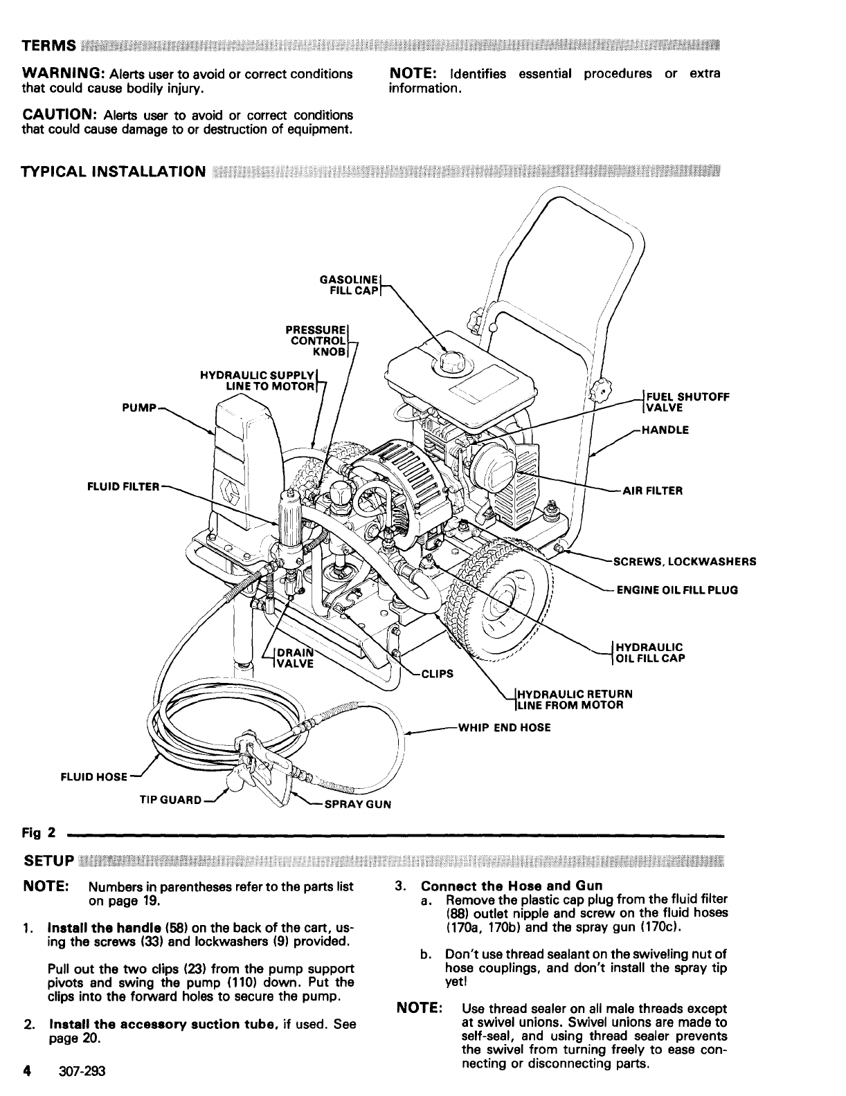
TYPICAL
INSTALLATION
FLUID HOSE
Fig 2
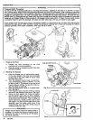
SETU P
U;;ti/'WH:nA
NOTE: Numbers in parentheses refer
to
the parts list
on page
19.
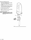
1.
Install
the
handle
(58)
on
the back
of
the cart, us-
ing the screws
(33)
and lockwashers
(9)
provided.
Pull
out
the
two
clips
(23)
from the pump support
pivots and swing the pump
(110)
down. Put the
clips into the forward
holes
to
secure the pump.
2.
Install
the
accessory
suction
tube,
if
used.
See
page
20.
4 307-293
NOTE: Identifies essential procedures or extra
information.
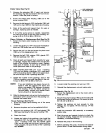
FUEL SHUTOFF
VALVE
~
IHYDRAULIC
--,
OIL FILL
CAP
HYDRAULIC RETURN
LINE
FROM MOTOR
'
___
WHIP
END HOSE
)
I
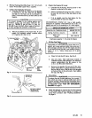
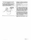
3.
Connect
the
Hose
and
Gun
a.
Remove the plastic cap plug from the fluid filter
(88)
outlet nipple and screw on the fluid hoses
(170a,
170b) and the spray gun (170cl.
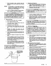
b.
Don't
use thread sealant on the swiveling
nut
of
hose couplings, and don't install the spray tip
yeti
NOTE:
Use
thread sealer on
all
male threads except
at
swivel unions. Swivel unions
are
made
to
self-seal, and using thread sealer prevents
the
swivel from turning freely
to
ease
con-
necting or disconnecting parts.