


16
307–758
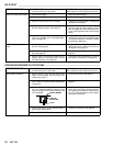
TROUBLESHOOTING
GUIDE
WARNING
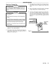
Pressure
Relief Procedure
T
o reduce the risk of serious bodily injury
, including
fluid injection, injury from splashing fluid or solvent in
the eyes or on the skin, moving parts or electric
shock, always follow this procedure whenever you
shut of
f the sprayer
, when checking or servicing any
part of the spray system, when installing, cleaning or
changing spray tips, and whenever you stop spray
-
ing.
1.
Engage the gun safety latch.
2.
T
urn the ON/OFF switch to OFF
.
3.
Unplug the power supply cord.
4.
Disengage the gun safety latch. Hold a metal
part of the gun firmly to a grounded metal pail.
T
rigger the gun to relieve pressure.
5.
Engage the gun safety latch.
6.
Open the pressure drain valve, having a con
-
tainer ready to catch the drainage. Leave the
pressure drain valve open until you are ready to
spray again.
If you suspect that the spray tip or hose is com
-
pletely clogged, or that pressure has not been fully
relieved after following the steps above,
VERY
SLOWL
Y loosen the tip guard retaining nut or hose
end coupling to relieve pressure gradually
, then
loosen completely
. Now clear the tip or hose ob
-
struction.
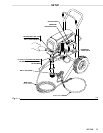
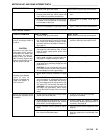
Check everything in the guide before disassembling the pump.
MOTOR
WON’T OPERA
TE
TYPE
OF PROBLEM
WHAT
T
O CHECK
If check is OK, go to next check
WHA
T T
O DO
When check is not OK refer to this column
Basic
Fluid Pressure Problems
1. Check
the pressure control knob setting. The
motor
will not run if it is at the minimum setting
(fully counterclockwise).
1. Slowly
increase the pressure setting to see
if
the motor starts.
2. Check for a clogged spray tip. Refer to the
separate
gun or tip instruction manual.
2. Relieve
pressure, refer to
the separate gun
or
tip instruction manual for tip cleaning.
Basic Mechanical Problems
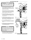
1.
Check for frozen or hardened paint in the
pump (74) and/or pressure control tube. Us-
ing
a screwdriver
, carefully try to rotate fan at
back
of motor by hand. See page 22.
1.
Thaw. Plug in sprayer and turn on. Slowly
increase pressure setting to see if motor
starts.
If it doesn’t, see NOTE 1, below
.
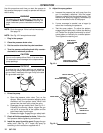
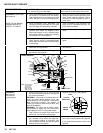
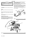
2. Check displacement pump connecting rod
pin (43). It must be completely pushed into
connecting
rod (70) and retaining spring (42)
must be firmly in groove of connecting rod.
See
Fig 38–3.
2. Push pin into place and secure with the
spring
retainer
.
3. Check for motor damage. Remove drive
housing assembly (73). See page 33. Try to
rotate
fan by hand.
3. Replace motor (75) if fan won’t turn. See
page
34.
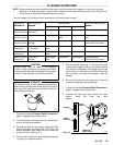
Basic Electrical Problems 1. Check
sprayer circuit breaker (309) button
to
be
sure it has not popped up.
1. Depress button to reset. If circuit breaker
continues
to open, see
‘Electrical Short’ on
page
21.
2. Check
electrical supply with volt meter
. Meter
should
read 105–125 V
AC.
2. Reset building circuit breaker; replace
building
fuse. T
ry another outlet.
3. Check extension cord for visible damage.
Use
a volt meter or test lamp at extension cord
outlet to check.
3.
Replace extension cord.
4. Check sprayer power supply cord (311) for
visible damage such as broken insulation or
wires.
4.
Replace
power supply cord. See page 20.
5. Check motor brush leads, terminals and
brush length. Brush length should be 1/2”
minimum.
See page 25.
5.
Tighten
terminal screws; replace brushes.
See
page 25.
NOTE
1:
Thaw the sprayer if water or water–based paint has frozen in it, due to exposure to low temperatures, by placing it in a warm
area.
Do not try to start the sprayer until it has thawed completely
. If the bourdon
tube was not damaged by the freezing, the pump
should
operate.
If paint hardened (dried) in the sprayer
, the pump packings and/or bare pressure control must be replaced. See page
36
(pump) or 29 (pressure control).