44
307–758
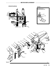
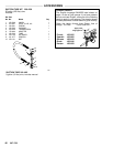
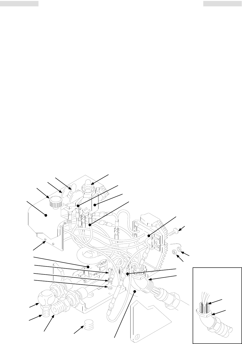
PARTS
DRA
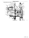
WING & LIST – PRESSURE CONTROL
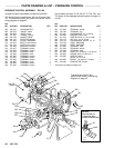
PRESSURE
CONTROL ASSEMBL
Y 220–455
Includes all items listed below
, except the terminals.
The terminals are included with the circuit board (item
72).
The terminals listed in
this parts list are shown on the
wiring
diagram on page 45.
Part
numbers for items
15, 23, 26, 50, 72, 75a, 75b, and
75c
shown in the drawings below are given
on pages 41
and
43.
REF
NO. PART NO. DESCRIPTION QTY
REF
NO. PART NO. DESCRIPTION QTY
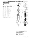
302 180–043 ,MICROSWITCH 1
303 105–679 .ON/OFF switch 1
304 105–659 .BOOT, switch 1
305 107–255 .GUARD, locking 1
306 218–168 JUMPER WIRE 1
308 218–170
RECTIFIER, bridge
1
309 107–256 CIRCUIT BREAKER 1
310 107–254 BOOT
, circuit breaker 1
311 218–169 CORD, power supply 1
312 107–268
ADAPTER, terminal
1
314 107–267
TERMINAL, female
1
315 107–293
TERMINAL, female
2
316 107–264
TERMINAL, male
1
317 107–396
TERMINAL, male
1
318 107–262
TERMINAL, female
1
319 107–260
TERMINAL, female
1
320 107–266
TERMINAL, female
1
321 103–885
TERMINAL, male
1
322 103–886
TERMINAL, female
3
323 107–265
TERMINAL, female
1
324 107–263
TERMINAL, female
1
325 102–799
TERMINAL, ring
1
327 157–021 LOCKW
ASHER, no. 8, internal
1
328 108–295 BUSHING, strain relief 1
331 101–273 SCREW
, flat hd, no. 10–24 x 5/8”
2
332 100–179 NUT
, hex, no. 10–24 thd
2
333 100–718 LOCKW
ASHER, internal, no. 10
2
334 178–797*
LABEL, W
ARNING 1
335 178–035*
LABEL, W
ARNING 1
336 107–261
TERMINAL, male
2
337 107–503
TERMINAL, female
1
338 107–504
TERMINAL, male
1
341 157–350
ADAPTER, 3/8 npt(m) x 1/4 npt (m)
1
342 100–840 ELBOW
, street, 1/4 npt(m x f)
1
343 100–035 SCREW
, slotted
pan hd, no. 8 x 5/16”
1
344 162–453
NIPPLE, 1/4 npt(m) x 1/4 npsm
1
345 108–460 CONNECT
OR, conduit
1
*Extra warning labels available free.
The
terminals listed in this
parts list are shown in the wiring
diagram on page 45.
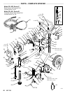
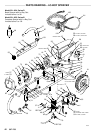
DETAIL
Shows
position of
conduit seal (26) in
conduit connector (345)
LABELS
26
345
01232
334,335
301
304
305
310
303
309
306
308
331
328
345
311
342
344
341
15
01225
Ref
72
343
327
325
302
332
333


