


307–758 29
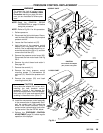
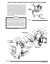
PRESSURE CONTROL REPLACEMENT
WARNING
To reduce the risk of serious injury,
follow the illustrated Pressure Relief
Procedure warning on page 24 when-
ever you are instructed to relieve pres-
sure.
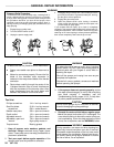
NOTE: Read the GENERAL REPAIR
INFORMATION on page 24 before
doing
this procedure.
NOTE:
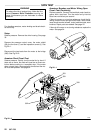
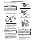
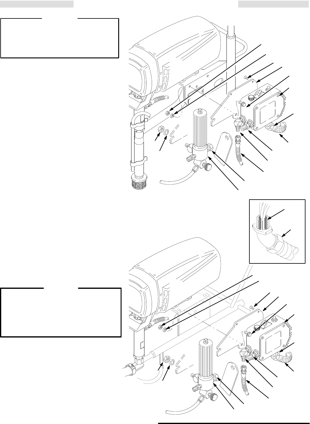
Refer to Fig 29–1 for this procedure.
1.
Relieve pressure.
2. Disconnect
the fluid outlet hoses.
Discon
-
nect the hose (68) between the pump and
pressure
control.
3.
Loosen the filter bracket nut (37).
4.
Hold the hex of the pressure control
adapter
(341) firmly with a 3/4” open end
wrench.
Use an adjustable wrench to
un
-
screw
the swivel union (38 or 5), and then
remove
the fluid filter (67).
5. Remove
the pressure control cover (62).
Disconnect
the four motor leads. See
Fig
28–2.
6.
Remove the circuit board and retain it.
See
page 28.
7.
Remove the conduit (1).
8.
Remove the three pressure control
mounting screws (7), lockwashers (9)
and
nuts (10). Remove the pressure con
-
trol.
9. Remove the screws (20) and back
mounting
bracket (64).
CAUTION
Do
not allow the adapter (341) to turn while
installing the new pressure control
assembly. Turning it can damage the
sensitive bourdon tube. Hold the adapter
firmly with a 3/4” open end wrench while
screwing
in the swivel union (38 or 5).
10. Install
the new
pressure control assembly
in the reverse order of disassembly
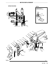
. Rein
-
stall the conduit seal (26) around the
wires in the conduit connector (345) to
prevent motor contamination from enter-
ing
the control. See the DET
AIL below
.
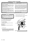
11. Perform the PRESSURE CONTROL
ADJUSTMENT, page 30, before regular
operation
of the sprayer
.
341
Fig 29–1
5
68
1
35,62
64
20
37
11
10
9
7
344
345
CAUTION
Do
not allow the adapter
(341) to turn at any time.
26
345
01232
01578
67
01588
37
11
341
38
68
1
64
20
10
9
7
344
67
35,62
345
UPRIGHT CART
LO-BOY CART