


38
307–758
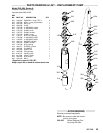
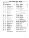
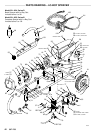
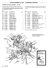
DISPLACEMENT PUMP REPAIR
219
PISTON
ASSEMBLY
218
TAPERED
END
Fig 38-1
0030
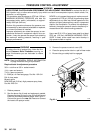
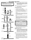
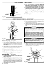
12. Slide the sleeve/piston rod assembly INTO THE
BOTTOM OF THE CYLINDER. This is to prevent
packing
damage during reassembly
. See Fig 38–1.
13. Screw
down the cylinder locknut (41) until
it is finger
tight
at the bottom of the external cylinder threads.
14. Place
the flats of the
intake valve (223) in a vise. In
-
stall a new o-ring (202*). Screw the pump cylinder
into the valve. Torque to 67 ft-lb (90 N.m). See Fig
37–3.
15. Install
the pump.
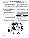
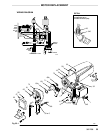
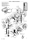
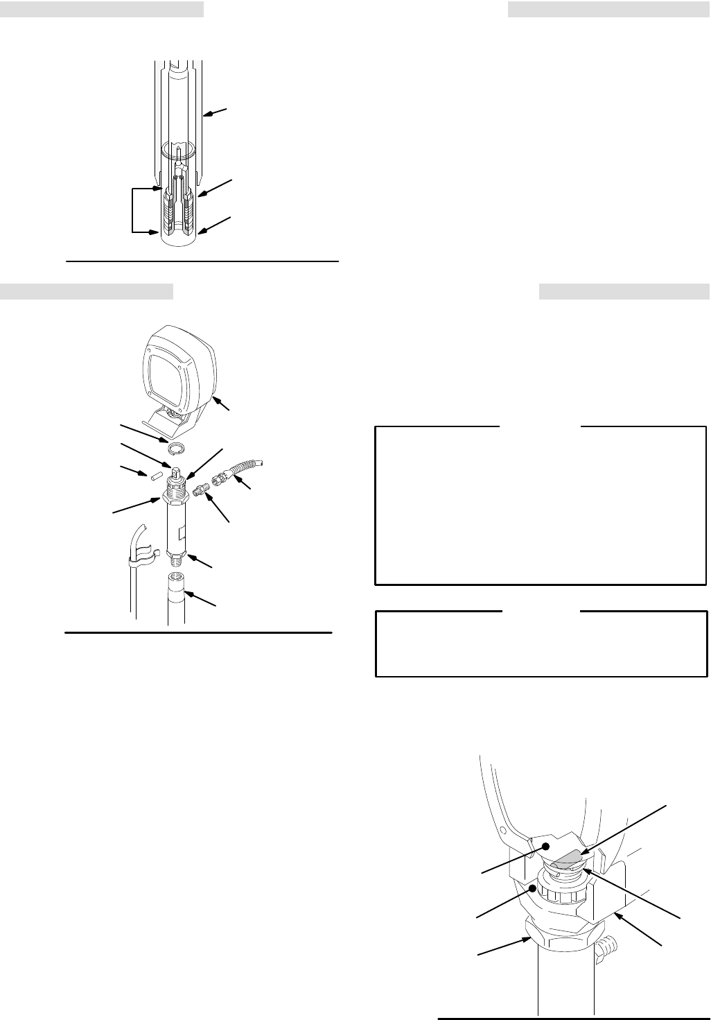
REMOVING AND INSTALLING A PUMP
Fig
38–2
73
42
43
41
68
223
224
39
61
216
01582
Remove the pump
See Fig 38–2.
1. Flush the pump. Relieve pressure. Stop the pump
with
the
piston rod (224) in its lowest position or care
-
fully
rotate the blades of the fan with a screwdriver to
lower
the rod.
2. While holding the pump intake valve (223) steady
with
a wrench, unscrew the suction tube (61).
3.
Disconnect the hose (68).
4. Push the retaining spring (42) up. Push out the pin
(43).
5. Loosen
the locknut (41) and unscrew the pump from
the
bearing housing (73).
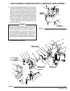
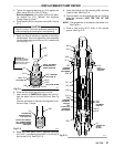
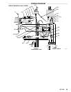
Install the pump See
Fig 38–3.
1. Screw
the displacement pump 3/4 of the way into the
bearing
housing (73).
2. Hold
the pin (43) up to the pin hole in the connecting
rod assembly (70) and continue screwing in the
pump
until the pin slides easily into the hole. Back
of
f
the pump until the top threads of the pump cylinder
are
flush with the face of the bearing housing and the
outlet
nipple (39) is straight back.
3. Push
the retaining spring (42)
into the groove all the
way
around the connecting rod.
4. Tighten
the locknut (41) very tight–about
70 ft-lb (97
N.m)–with
a 2 in. open–end wrench and a light ham
-
mer.
WARNING
Be sure the retaining spring (42) is firmly in the
groove
of the connecting rod, all the way around, to
prevent
it from working loose due to vibration. Refer
to
Fig 38–3.
If the pin works loose, parts could break off due to
the force of the pumping action. These parts
could
be projected through the air and result in serious
bodily
injury
, sprayer damage or property damage.
If the locknut (41) loosens during operation, the
threads of the bearing housing (73) will be dam-
aged.
Be sure to tighten the locknut firmly
.
CAUTION
5. Tighten the packing nut (216) just enough to stop
leakage, but no tighter. Fill the wet-cup/packing nut
1/3
full with Graco TSL. See Fig 38–2.
Fig 38–3
70
FACE
OF
BEARING
HOUSING
41
TORQUE TO
70 ft–lb
(95 N.m)
42
43
73
0031